
配置MSTP及負載均衡
阿新 • • 發佈:2018-05-14
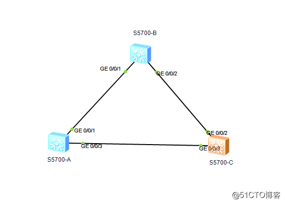
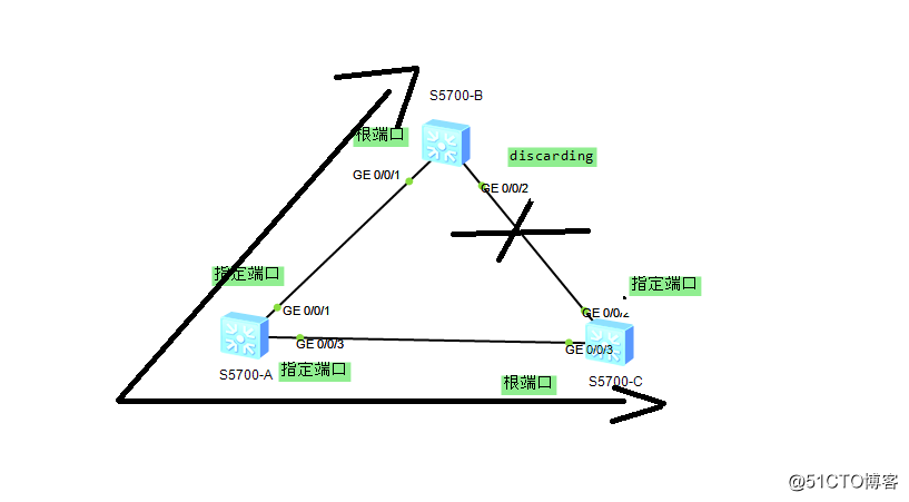
MSTP實現交換機負載均衡一、網絡拓撲圖
二、思路:
每臺交換機上新建vlan2,3,4,5。將交換機S5700-A作為VLAN2,3的根,交換機S5700-C作為VLAN4,5的根,驗證負載均衡以及備份
三、配置
1、每臺交換機新建VLAN2,3,4,5。將所有的端口都配置TRUNK模式。
命令如下:
system-view //進入系統視圖
vlan batch 2 to 5 //批量創建VLAN 2,3,4,5
quit //返回系統視圖
port-group 1 //創建端口組1
group-member GigabitEthernet 0/0/1 GigabitEthernet 0/0/3 //將端口加入端口組
undo shutdown //開啟端口組的端口
port trunk allow-pass vlan all //設置端口組的端口允許通過所有VLAN
quit //返回系統視圖
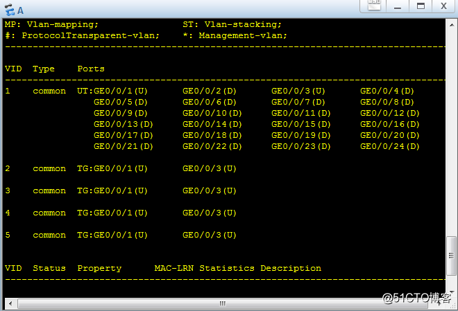
display vlan //查看vlan信息
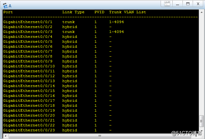
display port vlan //查看端口信息
將以上命令輸入到每臺交換機中,交換機的端口如圖
2、在每臺交換機配置MSTP域,並將vlan2,3,加入實例1,vlan4,5加入實例2。命令如下:
system-view //進入系統視圖
stp region-configuration //MSTP配置
region-name 1 //給MSTP域命名
instance 2 vlan 4 5 //新建實例2並將vlan4,加入
active region-configuration //激活MSTP域1
quit //返回系統視圖
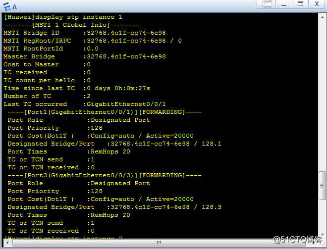
display stp instance 1 //查看instance1的信息
display stp insrance 2 //查看instance2的信息
每臺交換機執行以上命令
3、配置instance的值,交換機A的命令如下
system-view //進入系統視圖
stp instance 1 priority 0 //將instance 1的 priority的值設為0
交換機C的命令如下:
system-view //進入系統視圖
stp instance 1 priority 0 //將instance 1的 priority的值設為0
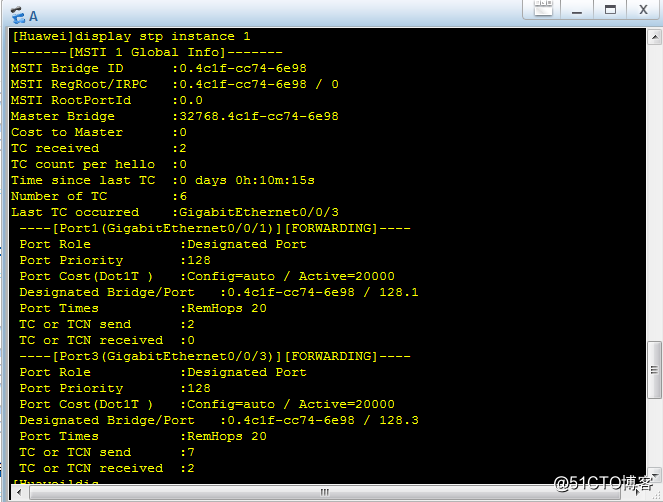
display stp instance 1 //查看instance 1的信息
4、驗證MSTP
在交換機A輸入以下命令:
system-view //進入系統視圖
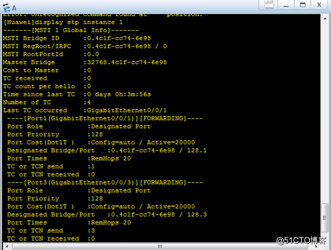
display stp instance 1 //查看instance1的信息
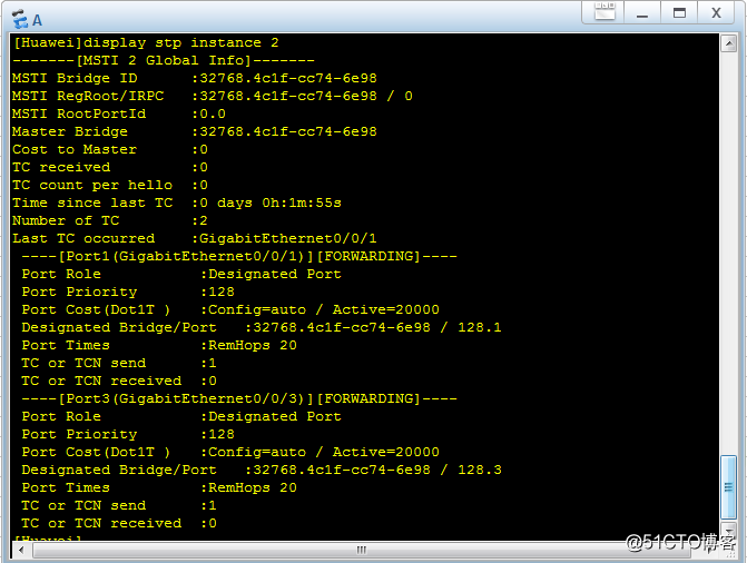
display stp instance 2 //查看instance2的信息
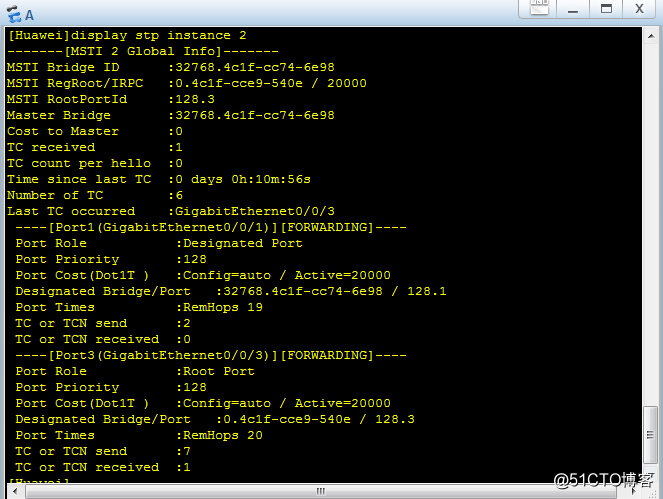
由圖可知交換機A中的instance1的MSTI Bridge ID為 0.4c1f-cc74-6e98也就是網橋ID。交換機A中的instance 2的MSTI Bridge ID 為32768.4c1f-cc74-6e98
在交換機C輸入以下命令:
system-view //進入系統視圖
display stp instance 1 //查看instance1的信息
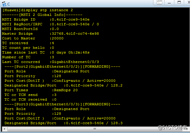
display stp instance 2 //查看instance2的信息
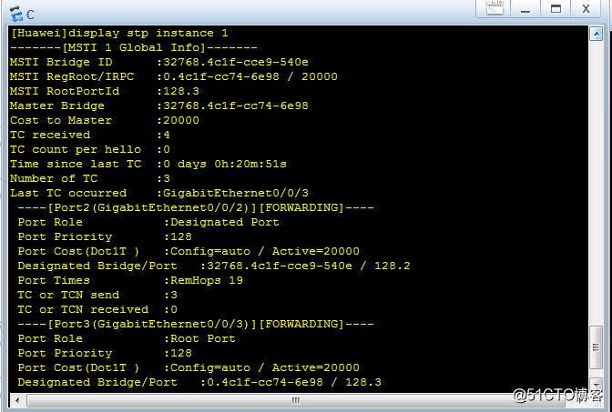
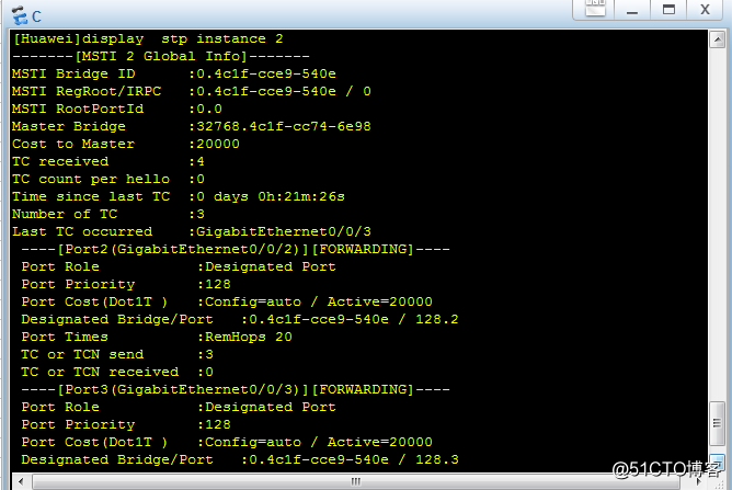
由圖可知交換機C中的instance1的MSTI Bridge ID為 32768.4c1f-cce9-540e。交換機A中的instance 2的MSTI Bridge ID 為0.4c1f-cce9-540e也就是網橋ID
5、驗證負載均衡
每臺交換機輸入以下命令:
system-view //進入系統視圖
display stp brief //查看stp信息
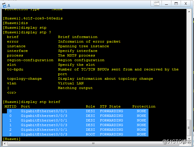
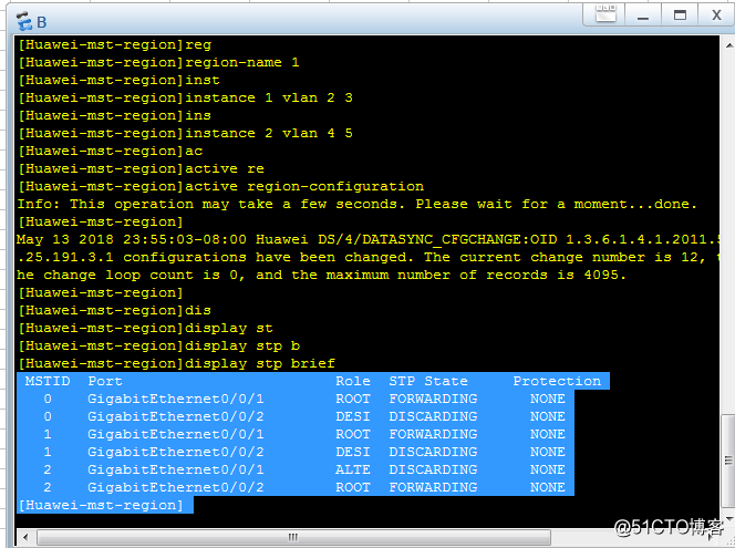
由上圖可知:
在instance 1中每個交換機的端口狀態,以及鏈路如下
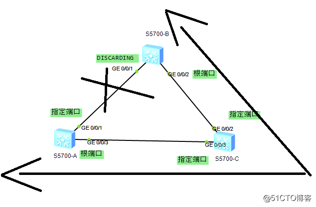
在instance 2中每個交換機的端口狀態,以及鏈路如下
二、思路:
每臺交換機上新建vlan2,3,4,5。將交換機S5700-A作為VLAN2,3的根,交換機S5700-C作為VLAN4,5的根,驗證負載均衡以及備份
三、配置
1、每臺交換機新建VLAN2,3,4,5。將所有的端口都配置TRUNK模式。
命令如下:
system-view //進入系統視圖
vlan batch 2 to 5 //批量創建VLAN 2,3,4,5
quit //返回系統視圖
port-group 1 //創建端口組1
group-member GigabitEthernet 0/0/1 GigabitEthernet 0/0/3 //將端口加入端口組
undo shutdown //開啟端口組的端口
port trunk allow-pass vlan all //設置端口組的端口允許通過所有VLAN
quit //返回系統視圖
display vlan //查看vlan信息
display port vlan //查看端口信息
將以上命令輸入到每臺交換機中,交換機的端口如圖
2、在每臺交換機配置MSTP域,並將vlan2,3,加入實例1,vlan4,5加入實例2。命令如下:
system-view //進入系統視圖
stp region-configuration //MSTP配置
region-name 1 //給MSTP域命名
instance 2 vlan 4 5 //新建實例2並將vlan4,加入
active region-configuration //激活MSTP域1
quit //返回系統視圖
display stp instance 1 //查看instance1的信息
display stp insrance 2 //查看instance2的信息
每臺交換機執行以上命令
3、配置instance的值,交換機A的命令如下
system-view //進入系統視圖
stp instance 1 priority 0 //將instance 1的 priority的值設為0
交換機C的命令如下:
system-view //進入系統視圖
stp instance 1 priority 0 //將instance 1的 priority的值設為0
display stp instance 1 //查看instance 1的信息
4、驗證MSTP
在交換機A輸入以下命令:
system-view //進入系統視圖
display stp instance 1 //查看instance1的信息
display stp instance 2 //查看instance2的信息
由圖可知交換機A中的instance1的MSTI Bridge ID為 0.4c1f-cc74-6e98也就是網橋ID。交換機A中的instance 2的MSTI Bridge ID 為32768.4c1f-cc74-6e98
在交換機C輸入以下命令:
system-view //進入系統視圖
display stp instance 1 //查看instance1的信息
display stp instance 2 //查看instance2的信息
由圖可知交換機C中的instance1的MSTI Bridge ID為 32768.4c1f-cce9-540e。交換機A中的instance 2的MSTI Bridge ID 為0.4c1f-cce9-540e也就是網橋ID
5、驗證負載均衡
每臺交換機輸入以下命令:
system-view //進入系統視圖
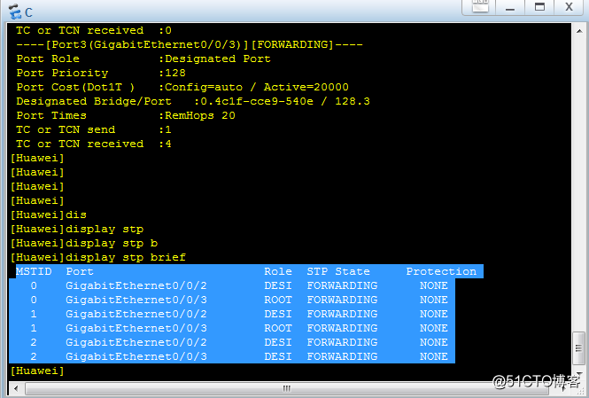
display stp brief //查看stp信息
由上圖可知:
在instance 1中每個交換機的端口狀態,以及鏈路如下
在instance 2中每個交換機的端口狀態,以及鏈路如下
配置MSTP及負載均衡