
RESTful風格的API介面
回顧:在網路通訊中,兩個路由器要想通訊,前提是必須有通往對端的路由;可以說路由是網路通訊的基礎條件;路由有很多種類,不同種類的路由資訊其特點,優缺點各不相同;最為簡單的就是直連路由,生成直連路由的必須滿足兩個條件,第一對應介面必須配置ip地址,其次對應介面物理和協議必須處於up狀態;優點是自動生成,管理員只需要把對應介面配置上相應的地址,連上網線,對應直連路由就可以生成;缺點:只能夠到達路由器直連的網路,不能夠到達非直連的網路;
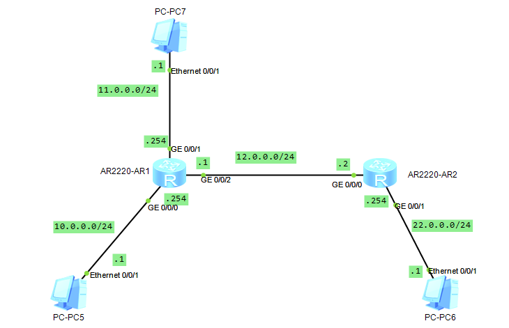
實驗:如下圖,配置好各裝置的介面ip地址以後,看看對應路由表的變化,看看pc5,pc7以及R1是否能夠ping同pc6?
分析:要想pc5,pc7和R1和pc6通訊,首先R1要有去往pc6的路由,其次pc5和pc7的閘道器指向R1,因為pc6和pc5pc7不在同一網路(不在同一網路的裝置通訊,預設將資料包傳送給閘道器);
未配置R1各介面ip地址前的路由表
| 1 2 3 4 5 6 7 8 9 10 11 12 13 14 15 16 17 18 19 20 21 22 23 24 25 26 27 28 29 30 |
<Huawei>dis ip int b
*down: administratively down
^down: standby
(l): loopback
(s): spoofing
The number of interface that is UPinPhysical is 4
The number of interface that is DOWNinPhysical is 0The number of interface that is UPinProtocol is 1
The number of interface that is DOWNinProtocol is 3
Interface IP Address/MaskPhysical Protocol
GigabitEthernet0/0/0unassigned up down
GigabitEthernet0/0/1unassigned up down
GigabitEthernet0/0/2unassigned up down
NULL0 unassigned up up(s)
<Huawei>dis ip rou
<Huawei>dis ip routing-tableRoute Flags: R - relay, D - download to fib
------------------------------------------------------------------------------
Routing Tables: Public
Destinations : 4 Routes : 4
Destination/MaskProto Pre Cost Flags NextHop Interface
127.0.0.0/8Direct 0 0 D 127.0.0.1 InLoopBack0
127.0.0.1/32Direct 0 0 D 127.0.0.1 InLoopBack0
127.255.255.255/32Direct 0 0 D 127.0.0.1 InLoopBack0
255.255.255.255/32Direct 0 0 D 127.0.0.1 InLoopBack0
<Huawei>
|
提示:可以看到在未配置介面ip地址前,檢視路由表,路由表中只有迴環介面的路由資訊;檢視介面簡要資訊也可以發現對應介面的物理狀態是up的,協議狀態是down,不滿足生成直連路由的條件,所以路由表沒有對應介面的路由資訊;
配置R1
| 1 2 3 4 5 6 7 8 9 10 11 12 13 14 15 16 17 18 19 20 21 22 23 24 25 26 27 28 29 30 31 32 33 34 35 36 37 38 39 40 41 42 43 44 45 46 47 48 49 50 51 52 53 |
<Huawei>sys
Enter system view,returnuser view with Ctrl+Z.
[Huawei]sys R1
[R1]int g0/0/0
[R1-GigabitEthernet0/0/0]ip add 10.0.0.254 24
Jul 2 2021 23:00:05-08:00 R1 %%01IFNET/4/LINK_STATE(l)[0]:The line protocol IP on the interface GigabitEthernet0/0/0has entered the UP state. int g0/0/1
[R1-GigabitEthernet0/0/0]
[R1-GigabitEthernet0/0/1]ip add 11.0.0.254 24
[R1-GigabitEthernet0/0/1]int g0/0/2
[R1-GigabitEthernet0/0/2]ip add 12.0.0.1 24
Jul 2 2021 23:00:05-08:00 R1 %%01IFNET/4/LINK_STATE(l)[1]:The line protocol IP on the interface GigabitEthernet0/0/1has entered the UP state.
[R1-GigabitEthernet0/0/2]ip add 12.0.0.1 24
Jul 2 2021 23:00:07-08:00 R1 %%01IFNET/4/LINK_STATE(l)[2]:The line protocol IP on the interface GigabitEthernet0/0/2has entered the UP state.
[R1-GigabitEthernet0/0/2]q
[R1]dis ip int b
*down: administratively down
^down: standby
(l): loopback
(s): spoofing
The number of interface that is UPinPhysical is 4
The number of interface that is DOWNinPhysical is 0
The number of interface that is UPinProtocol is 4
The number of interface that is DOWNinProtocol is 0
Interface IP Address/MaskPhysical Protocol
GigabitEthernet0/0/010.0.0.254/24up up
GigabitEthernet0/0/111.0.0.254/24up up
GigabitEthernet0/0/212.0.0.1/24up up
NULL0 unassigned up up(s)
[R1]dis ip rou
[R1]dis ip routing-table
Route Flags: R - relay, D - download to fib
------------------------------------------------------------------------------
Routing Tables: Public
Destinations : 13 Routes : 13
Destination/MaskProto Pre Cost Flags NextHop Interface
10.0.0.0/24Direct 0 0 D 10.0.0.254 GigabitEthernet0/0/0
10.0.0.254/32Direct 0 0 D 127.0.0.1 GigabitEthernet0/0/0
10.0.0.255/32Direct 0 0 D 127.0.0.1 GigabitEthernet0/0/0
11.0.0.0/24Direct 0 0 D 11.0.0.254 GigabitEthernet0/0/1
11.0.0.254/32Direct 0 0 D 127.0.0.1 GigabitEthernet0/0/1
11.0.0.255/32Direct 0 0 D 127.0.0.1 GigabitEthernet0/0/1
12.0.0.0/24Direct 0 0 D 12.0.0.1 GigabitEthernet0/0/2
12.0.0.1/32Direct 0 0 D 127.0.0.1 GigabitEthernet0/0/2
12.0.0.255/32Direct 0 0 D 127.0.0.1 GigabitEthernet0/0/2
127.0.0.0/8Direct 0 0 D 127.0.0.1 InLoopBack0
127.0.0.1/32Direct 0 0 D 127.0.0.1 InLoopBack0
127.255.255.255/32Direct 0 0 D 127.0.0.1 InLoopBack0
255.255.255.255/32Direct 0 0 D 127.0.0.1 InLoopBack0
[R1]
|
提示:可以看到在r1上的各介面上正確的配置上ip地址資訊以後,對應介面的協議狀態就從down轉變為up狀態,同時路由表中也多了對應網路的路由資訊;
配置R2
| 1 2 3 4 5 6 7 8 9 10 11 12 13 14 15 16 17 18 19 20 21 22 23 24 25 26 27 28 29 30 31 32 33 34 35 36 37 38 39 40 41 42 43 44 45 46 47 |
<Huawei>sys
Enter system view,returnuser view with Ctrl+Z.
[Huawei]sys R2
[R2]int g0/0/0
[R2-GigabitEthernet0/0/0]ip add 12.0.0.2 24
[R2-GigabitEthernet0/0/0]int g0/0/1
Jul 2 2021 23:05:39-08:00 R2 %%01IFNET/4/LINK_STATE(l)[2]:The line protocol IP on the interface GigabitEthernet0/0/0has entered the UP state.
[R2-GigabitEthernet0/0/0]int g0/0/1
[R2-GigabitEthernet0/0/1]ip add 22.0.0.254 24
Jul 2 2021 23:05:40-08:00 R2 %%01IFNET/4/LINK_STATE(l)[3]:The line protocol IP on the interface GigabitEthernet0/0/1has entered the UP state.
[R2-GigabitEthernet0/0/1]q
[R2]dis ip int b
*down: administratively down
^down: standby
(l): loopback
(s): spoofing
The number of interface that is UPinPhysical is 3
The number of interface that is DOWNinPhysical is 1
The number of interface that is UPinProtocol is 3
The number of interface that is DOWNinProtocol is 1
Interface IP Address/MaskPhysical Protocol
GigabitEthernet0/0/012.0.0.2/24up up
GigabitEthernet0/0/122.0.0.254/24up up
GigabitEthernet0/0/2unassigned down down
NULL0 unassigned up up(s)
[R2]dis ip rout
[R2]dis ip routing-table
Route Flags: R - relay, D - download to fib
------------------------------------------------------------------------------
Routing Tables: Public
Destinations : 10 Routes : 10
Destination/MaskProto Pre Cost Flags NextHop Interface
12.0.0.0/24Direct 0 0 D 12.0.0.2 GigabitEthernet0/0/0
12.0.0.2/32Direct 0 0 D 127.0.0.1 GigabitEthernet0/0/0
12.0.0.255/32Direct 0 0 D 127.0.0.1 GigabitEthernet0/0/0
22.0.0.0/24Direct 0 0 D 22.0.0.254 GigabitEthernet0/0/1
22.0.0.254/32Direct 0 0 D 127.0.0.1 GigabitEthernet0/0/1
22.0.0.255/32Direct 0 0 D 127.0.0.1 GigabitEthernet0/0/1
127.0.0.0/8Direct 0 0 D 127.0.0.1 InLoopBack0
127.0.0.1/32Direct 0 0 D 127.0.0.1 InLoopBack0
127.255.255.255/32Direct 0 0 D 127.0.0.1 InLoopBack0
255.255.255.255/32Direct 0 0 D 127.0.0.1 InLoopBack0
[R2]
|
提示:按照題意我們配置好了兩個路由器的名稱和相關介面的ip地址,對應路由器各自都生成了相應的直連路由;
配置好各pc的ip地址資訊,然後用pc5ping pc6看看是否可以正常通訊?
配置pc5
提示:pc5和R1的g0/0/0口是直連,所以對應pc5的閘道器必須指向R1的g0/0/0介面的ip地址;
配置pc6
提示:pc6和R2的g0/0/1口是直連,所以對應pc6的閘道器必須指向R2的g0/0/1介面的ip地址;
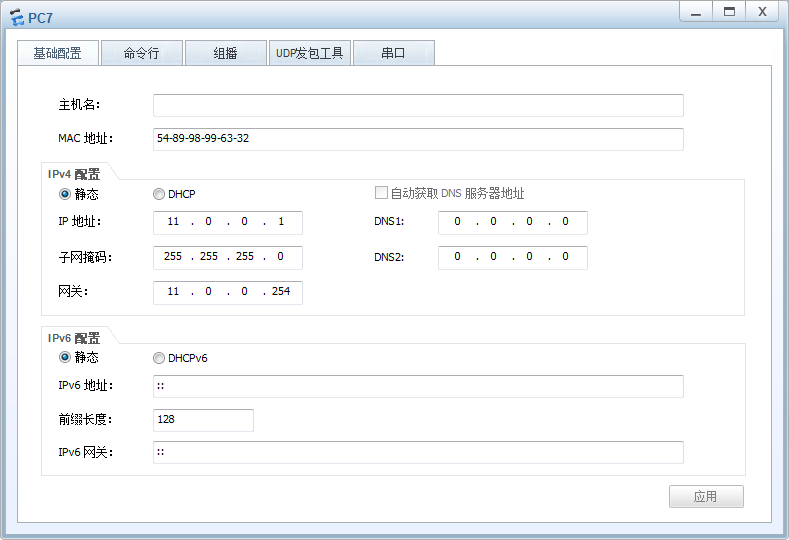
配置pc7
提示:pc7和R1的g0/0/1口是直連,所以對應pc7的閘道器必須指向R1的g0/0/1介面的ip地址;
驗證:pc5 ping pc6看看是否可以通訊?
| 1 2 3 4 5 6 7 8 9 10 11 12 13 14 15 16 17 18 19 20 21 22 23 24 25 26 |
PC>ipconfig
LinklocalIPv6 address...........: fe80::5689:98ff:fe54:5adc
IPv6 address......................: :: / 128
IPv6 gateway......................: ::
IPv4 address......................: 10.0.0.1
Subnet mask.......................: 255.255.255.0
Gateway...........................: 10.0.0.254
Physical address..................: 54-89-98-54-5A-DC
DNS server........................:
PC>ping22.0.0.1
Ping 22.0.0.1: 32 data bytes, Press Ctrl_C tobreak
Request timeout!
Request timeout!
Request timeout!
Request timeout!
Request timeout!
--- 22.0.0.1pingstatistics ---
5 packet(s) transmitted
0 packet(s) received
100.00% packet loss
PC>
|
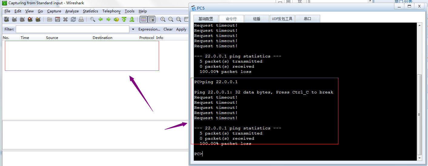
提示:可以看到在pc5上ping pc6,給我們的回饋是請求超時;
在r1的g0/0/2口抓包,看看對應是否有資料包通過?
提示:可以看到在R1的g0/0/2口上沒有抓到任何資料包,說明ping22.0.0.1的資料包沒有在r1和r2直連鏈路上通過,所以我們ping pc6回饋給我們的是請求超時,其原因是R1上沒有去往pc6的路由,當R1收到pc5發來的資料包,檢視對應資料包是去往22.0.0.1的,R1在自己的路由表中沒有匹配到去往22.0.0.1的路由,所以R1直接將對應資料包丟棄,不予轉發;
驗證:用pc5 ping pc7 看看是否能夠正常通訊?
| 1 2 3 4 5 6 7 8 9 10 11 12 13 14 15 16 17 18 19 20 21 22 23 24 25 26 27 |
PC>ipconfig
LinklocalIPv6 address...........: fe80::5689:98ff:fe54:5adc
IPv6 address......................: :: / 128
IPv6 gateway......................: ::
IPv4 address......................: 10.0.0.1
Subnet mask.......................: 255.255.255.0
Gateway...........................: 10.0.0.254
Physical address..................: 54-89-98-54-5A-DC
DNS server........................:
PC>ping11.0.0.1
Ping 11.0.0.1: 32 data bytes, Press Ctrl_C tobreak
Request timeout!
From 11.0.0.1: bytes=32seq=2 ttl=127time=16 ms
From 11.0.0.1: bytes=32seq=3 ttl=127time=16 ms
From 11.0.0.1: bytes=32seq=4 ttl=127time=16 ms
From 11.0.0.1: bytes=32seq=5 ttl=127time<1 ms
--- 11.0.0.1pingstatistics ---
5 packet(s) transmitted
4 packet(s) received
20.00% packet loss
round-trip min/avg/max= 0/12/16ms
PC>
|
提示:可以看到pc5 是可以正常和pc7通訊;其實原因很簡單,就是因為R1上有對應去往pc7和pc5的直連路由,所以pc5和pc7可以正常通訊;通過上述實驗,可以看到直連路由的優點是它自動生成,只要管理員正確配置了ip地址,並且在介面上接上了線,對應直連路由就會自動生成了;缺點就是不能和非直連的網路通訊;這樣一來我們要想和非直連網路通訊,光憑直連路由是做不到;
靜態路由
所謂靜態路由就是指管理員人工手動新增的路由資訊;
新增靜態路由的命令語法
| 1 |
ip route-static 目標網路 子網掩碼/字首 下一跳地址/出介面
|
提示:如果出介面為乙太網介面,則必須要指定下一跳地址,如果出介面為串列埠,可以使用下一跳或出介面來配置;
實驗:還是上面的top,實現pc5能夠ping 通pc6
在R1上新增靜態路由
驗證:現在R1上有去往pc6的路由資訊,用pc 5ping pc6 看看是否可以正常通訊?
| 1 2 3 4 5 6 7 8 9 10 11 12 13 14 15 16 17 18 19 20 21 22 23 24 25 26 |
PC>ipconfig
LinklocalIPv6 address...........: fe80::5689:98ff:fe54:5adc
IPv6 address......................: :: / 128
IPv6 gateway......................: ::
IPv4 address......................: 10.0.0.1
Subnet mask.......................: 255.255.255.0
Gateway...........................: 10.0.0.254
Physical address..................: 54-89-98-54-5A-DC
DNS server........................:
PC>ping22.0.0.1
Ping 22.0.0.1: 32 data bytes, Press Ctrl_C tobreak
Request timeout!
Request timeout!
Request timeout!
Request timeout!
Request timeout!
--- 22.0.0.1pingstatistics ---
5 packet(s) transmitted
0 packet(s) received
100.00% packet loss
PC>
|
提示:可以看到pc5現在依然ping 不通pc6;
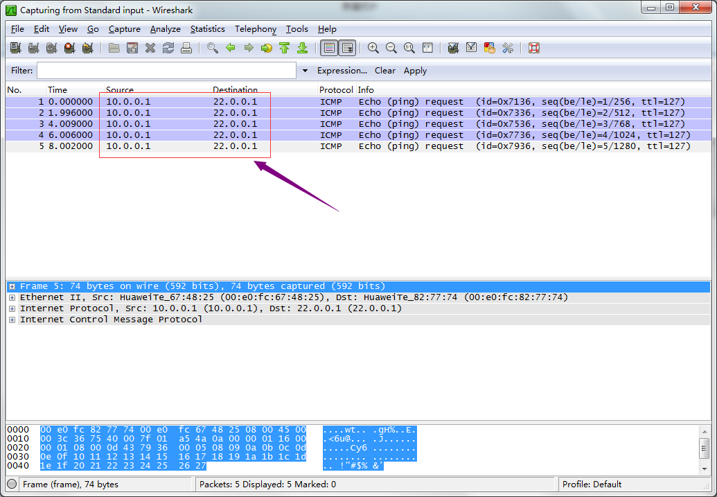
在r1的g0/0/2口抓包,看看是否有對應資料包通過?
提示:現在在R1的g0/0/2口可以抓到pc5 ping pc 6的包,但是沒有pc6 回來的包,其原因是R2上沒有到達pc5所在網路的路由;所以pc5 ping 不同pc6;
在R2上新增去往pc5的路由
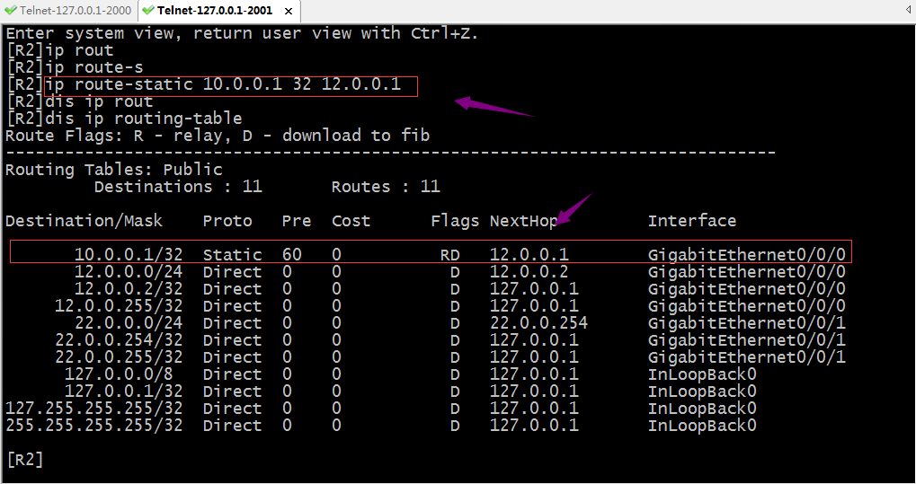
驗證:現在用pc5再次ping pc6看看是否能通?
| 1 2 3 4 5 6 7 8 9 10 11 12 13 14 15 16 17 18 19 20 21 22 23 24 25 26 27 |
PC>ipconfig
LinklocalIPv6 address...........: fe80::5689:98ff:fe54:5adc
IPv6 address......................: :: / 128
IPv6 gateway......................: ::
IPv4 address......................: 10.0.0.1
Subnet mask.......................: 255.255.255.0
Gateway...........................: 10.0.0.254
Physical address..................: 54-89-98-54-5A-DC
DNS server........................:
PC>ping22.0.0.1
Ping 22.0.0.1: 32 data bytes, Press Ctrl_C tobreak
Request timeout!
From 22.0.0.1: bytes=32seq=2 ttl=126time=16 ms
From 22.0.0.1: bytes=32seq=3 ttl=126time=16 ms
From 22.0.0.1: bytes=32seq=4 ttl=126time=16 ms
From 22.0.0.1: bytes=32seq=5 ttl=126time=16 ms
--- 22.0.0.1pingstatistics ---
5 packet(s) transmitted
4 packet(s) received
20.00% packet loss
round-trip min/avg/max= 0/16/16ms
PC>
|
提示:可以看到pc5可以正常ping 通pc6了;
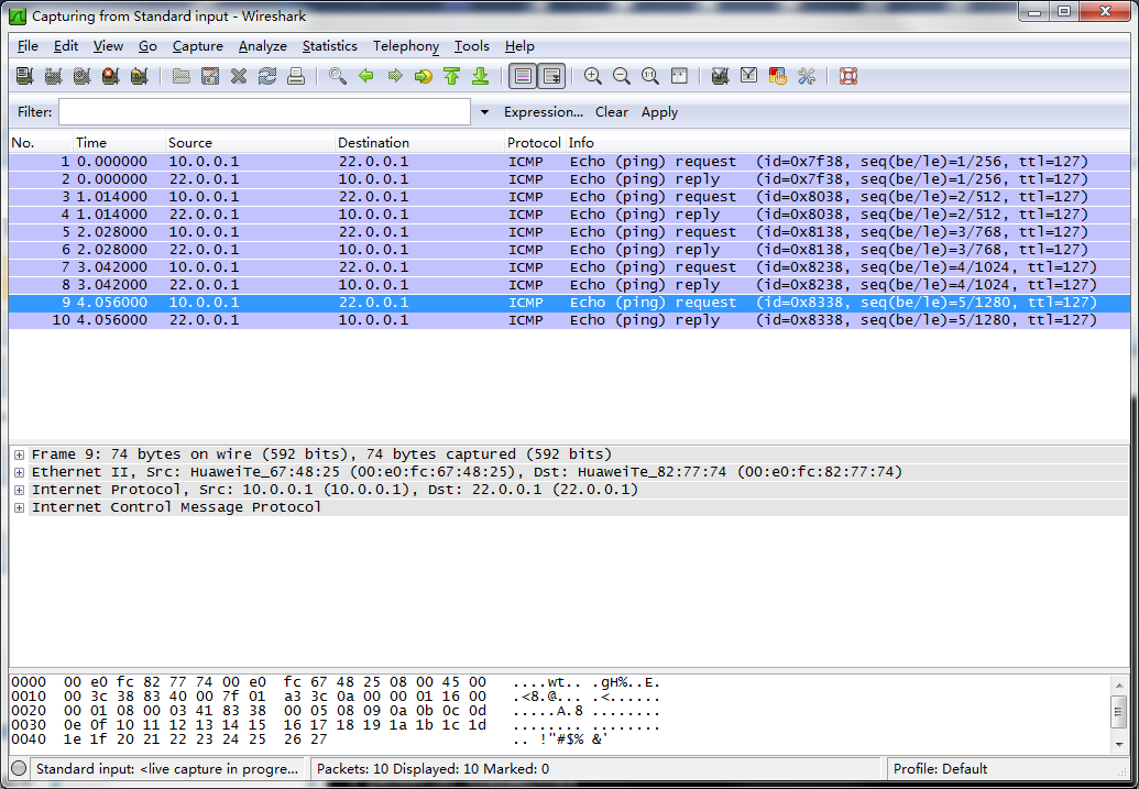
驗證:在R1的g0/0/2口抓包,看看對應資料包是否有回覆了?
提示:可以看到現在在R1的g0/0/2口抓包就有正常回復包;
驗證:pc7 ping pc6,看看是否能夠ping通?
| 1 2 3 4 5 6 7 8 9 10 11 12 13 14 15 16 17 18 19 20 21 22 23 24 25 26 |
PC>ipconfig
LinklocalIPv6 address...........: fe80::5689:98ff:fe99:6332
IPv6 address......................: :: / 128
IPv6 gateway......................: ::
IPv4 address......................: 11.0.0.1
Subnet mask.......................: 255.255.255.0
Gateway...........................: 11.0.0.254
Physical address..................: 54-89-98-99-63-32
DNS server........................:
PC>ping22.0.0.1
Ping 22.0.0.1: 32 data bytes, Press Ctrl_C tobreak
Request timeout!
Request timeout!
Request timeout!
Request timeout!
Request timeout!
--- 22.0.0.1pingstatistics ---
5 packet(s) transmitted
0 packet(s) received
100.00% packet loss
PC>
|
提示:可以看到pc7到現在依然無法Ping通pc6,其原因是r2沒有回來pc7的路由,所以pc7現在能夠把包送達到pc6,但回不來,所以導致pc7ping不同pc6;要想實現pc7ping通pc6,我們還需要在r2上新增一條去往pc7的路由;
在R2上新增去往pc7的路由
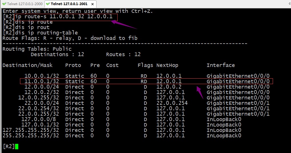
驗證:現在pc7 ping pc6,看看是否可以正常通訊?
| 1 2 3 4 5 6 7 8 9 10 11 12 13 14 15 16 17 18 19 20 21 22 23 24 25 26 27 |
PC>ipconfig
LinklocalIPv6 address...........: fe80::5689:98ff:fe99:6332
IPv6 address......................: :: / 128
IPv6 gateway......................: ::
IPv4 address......................: 11.0.0.1
Subnet mask.......................: 255.255.255.0
Gateway...........................: 11.0.0.254
Physical address..................: 54-89-98-99-63-32
DNS server........................:
PC>ping22.0.0.1
Ping 22.0.0.1: 32 data bytes, Press Ctrl_C tobreak
From 22.0.0.1: bytes=32seq=1 ttl=126time=16 ms
From 22.0.0.1: bytes=32seq=2 ttl=126time=16 ms
From 22.0.0.1: bytes=32seq=3 ttl=126time=16 ms
From 22.0.0.1: bytes=32seq=4 ttl=126time=16 ms
From 22.0.0.1: bytes=32seq=5 ttl=126time=16 ms
--- 22.0.0.1pingstatistics ---
5 packet(s) transmitted
5 packet(s) received
0.00% packet loss
round-trip min/avg/max= 16/16/16ms
PC>
|
提示:可以看到pc7現在也能正常ping通pc6;通過上述實驗我們發現靜態路由的配置還是很簡單,必須手動指定目標網路,掩碼以及下一跳;其次網路通訊的過程是是雙向的,配置靜態路由,我們必須考慮來回的路由在所經過的路由器都要有對應的路由;如果網路規模非常大(網段特別多,路由器特別多),如果用手動配置靜態路由的方式,就不是很容易了;所以靜態路由適用於網路規模不是太大的環境中;除此之外靜態路由有一個非常大的缺點,它不能根據top變化而變化,這樣一來,如果現網中某個介面地址的發生變化,管理員必須手動更改路由資訊;
負載分擔
負載分擔就是等價路由即到達同一目標網路的路由有多條,並且他們的優先順序開銷都一樣;
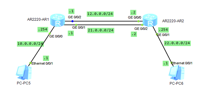
實驗:如下圖,配置pc5和pc6通訊的流量都可以走R1,R2之間的兩條鏈路
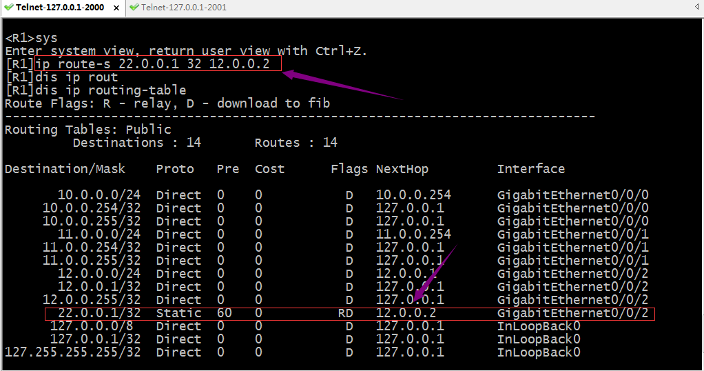
在R1的g0/0/1介面上配置對應的ip地址,並配置訪問pc6的對應路由資訊
| 1 2 3 4 5 6 7 8 9 10 11 12 13 14 15 16 17 18 19 20 21 22 23 24 25 26 27 28 29 30 31 32 |
<R1>sys
Enter system view,returnuser view with Ctrl+Z.
[R1]int g0/0/1
[R1-GigabitEthernet0/0/1]ip add 21.0.0.1 24
[R1-GigabitEthernet0/0/1]q
[R1]ip route-s 22.0.0.1 32 21.0.0.2
[R1]dis ip routin
[R1]dis ip routing-table
Route Flags: R - relay, D - download to fib
------------------------------------------------------------------------------
Routing Tables: Public
Destinations : 14 Routes : 15
Destination/MaskProto Pre Cost Flags NextHop Interface
10.0.0.0/24Direct 0 0 D 10.0.0.254 GigabitEthernet0/0/0
10.0.0.254/32Direct 0 0 D 127.0.0.1 GigabitEthernet0/0/0
10.0.0.255/32Direct 0 0 D 127.0.0.1 GigabitEthernet0/0/0
12.0.0.0/24Direct 0 0 D 12.0.0.1 GigabitEthernet0/0/2
12.0.0.1/32Direct 0 0 D 127.0.0.1 GigabitEthernet0/0/2
12.0.0.255/32Direct 0 0 D 127.0.0.1 GigabitEthernet0/0/2
21.0.0.0/24Direct 0 0 D 21.0.0.1 GigabitEthernet0/0/1
21.0.0.1/32Direct 0 0 D 127.0.0.1 GigabitEthernet0/0/1
21.0.0.255/32Direct 0 0 D 127.0.0.1 GigabitEthernet0/0/1
22.0.0.1/32Static 60 0 RD 12.0.0.2 GigabitEthernet0/0/2
Static 60 0 RD 21.0.0.2 GigabitEthernet0/0/1
127.0.0.0/8Direct 0 0 D 127.0.0.1 InLoopBack0
127.0.0.1/32Direct 0 0 D 127.0.0.1 InLoopBack0
127.255.255.255/32Direct 0 0 D 127.0.0.1 InLoopBack0
255.255.255.255/32Direct 0 0 D 127.0.0.1 InLoopBack0
[R1]
|
在R2的g0/0/2介面上配置對應的ip地址,並配置訪問pc5的對應路由資訊
| 1 2 3 4 5 6 7 8 9 10 11 12 13 14 15 16 17 18 19 20 21 22 23 24 25 26 27 28 29 30 31 32 33 34 |
<R2>sys
Enter system view,returnuser view with Ctrl+Z.
[R2]int g0/0/2
[R2-GigabitEthernet0/0/2]ip add 21.0.0.2 24
Jul 3 2021 00:34:04-08:00 R2 %%01IFNET/4/LINK_STATE(l)[0]:The line protocol IP on the interface GigabitEthernet0/0/2has entered the UP state.
[R2-GigabitEthernet0/0/2]q
[R2]ip route-s 10.0.0.1 32 21.0.0.1
[R2]dis ip routing
[R2]dis ip routing-table
Route Flags: R - relay, D - download to fib
------------------------------------------------------------------------------
Routing Tables: Public
Destinations : 15 Routes : 16
Destination/MaskProto Pre Cost Flags NextHop Interface
10.0.0.1/32Static 60 0 RD 12.0.0.1 GigabitEthernet0/0/0
Static 60 0 RD 21.0.0.1 GigabitEthernet0/0/2
11.0.0.1/32Static 60 0 RD 12.0.0.1 GigabitEthernet0/0/0
12.0.0.0/24Direct 0 0 D 12.0.0.2 GigabitEthernet0/0/0
12.0.0.2/32Direct 0 0 D 127.0.0.1 GigabitEthernet0/0/0
12.0.0.255/32Direct 0 0 D 127.0.0.1 GigabitEthernet0/0/0
21.0.0.0/24Direct 0 0 D 21.0.0.2 GigabitEthernet0/0/2
21.0.0.2/32Direct 0 0 D 127.0.0.1 GigabitEthernet0/0/2
21.0.0.255/32Direct 0 0 D 127.0.0.1 GigabitEthernet0/0/2
22.0.0.0/24Direct 0 0 D 22.0.0.254 GigabitEthernet0/0/1
22.0.0.254/32Direct 0 0 D 127.0.0.1 GigabitEthernet0/0/1
22.0.0.255/32Direct 0 0 D 127.0.0.1 GigabitEthernet0/0/1
127.0.0.0/8Direct 0 0 D 127.0.0.1 InLoopBack0
127.0.0.1/32Direct 0 0 D 127.0.0.1 InLoopBack0
127.255.255.255/32Direct 0 0 D 127.0.0.1 InLoopBack0
255.255.255.255/32Direct 0 0 D 127.0.0.1 InLoopBack0
[R2]
|
提示:這樣配置以後,pc5所在網路和pc6所在網路的裝置通訊就有兩條鏈路一起負載,這樣可以減少之前一條鏈路的壓力;
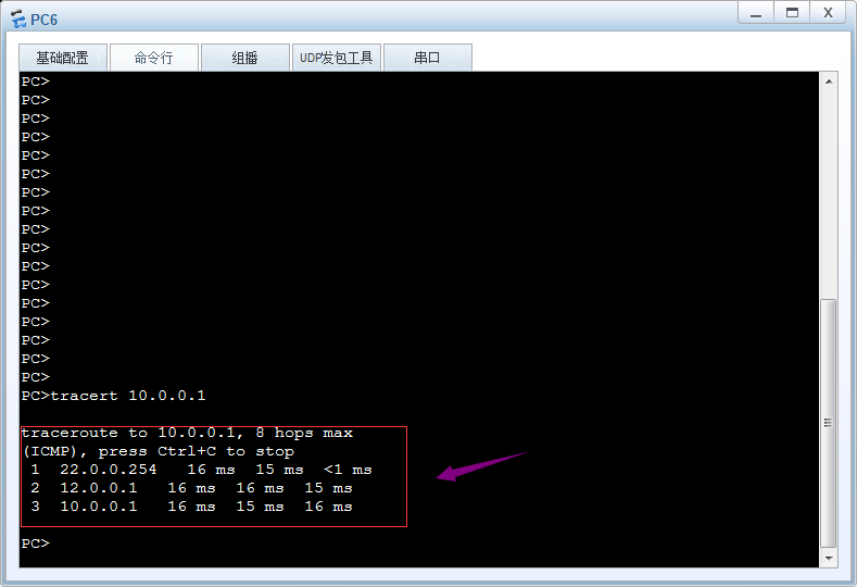
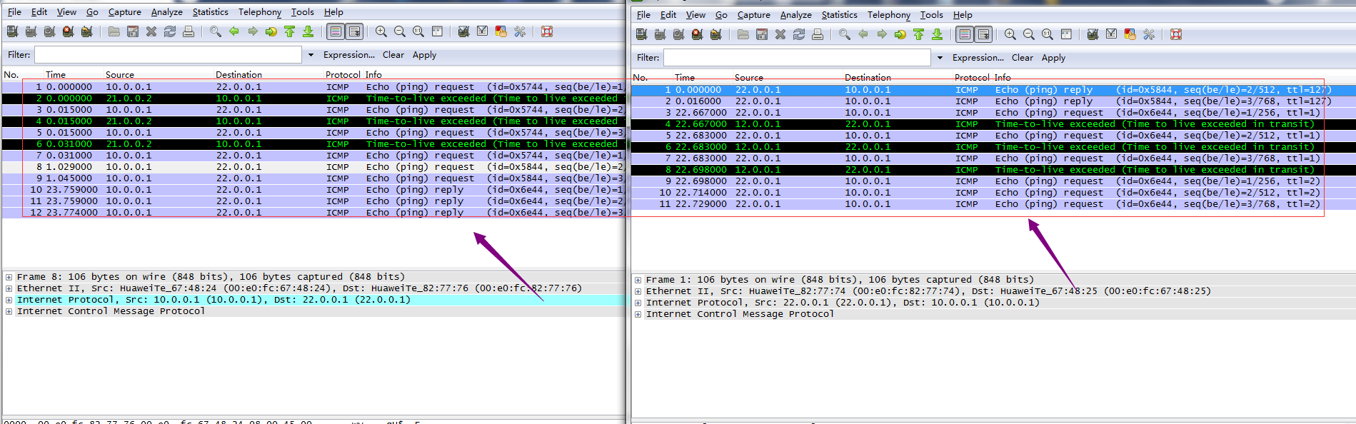
驗證:用tracert 追蹤pc5和pc6通訊所走的鏈路
提示:從上面的鏈路追蹤和抓包可以看到現在pc5和pc6通訊,兩條鏈路都用上了,pc5pingpc6走下面21網段,回覆包全部走12網段所在鏈路,pc6pingpc5 去走12網段所在鏈路,回來走21網段所在鏈路;
浮動路由
浮動路由又稱主備路由,即去往同一網路的多條路由中有主備之分,預設情況主路由工作(活動路由),一旦活動路由宕掉,備份路由馬上就變為活動路由;一旦主路由恢復,備份路由又會處於非活動狀態;有點類似keepalived的搶佔模式,一旦主掛了,備份路由馬上變為主,一旦原來的主活了,現在的主馬上就變為備份路由;其原理就是在等價路由的基礎上,藉助路由器轉發原則根據其優先順序來確定那條路由存在路由表(最優路由),一旦存在路由表中的最優路由鏈路宕掉,對應介面也會隨之宕掉,所以對應最優路由來說,其出介面就會變為unknow狀態,導致路由不可用,此時根據路由轉發原則,原來的次優路由就會變為最優路由,一旦優先順序最小的路由所在鏈路恢復正常,路由器又會根據路由轉發原則把次優路由替換下來,讓其處於非活動狀態;
實驗:還是上述top,在R1上配置12網段所在鏈路為主鏈路,21網段為備份鏈路
配置r1
| 1 2 3 4 5 6 7 8 9 10 11 12 13 14 15 16 17 18 19 20 21 22 23 24 25 26 27 28 29 30 31 32 33 34 35 36 37 38 39 40 41 |
[R1]dis ip routing-table protocol static
Route Flags: R - relay, D - download to fib
------------------------------------------------------------------------------
Public routing table : Static
Destinations : 1 Routes : 2 Configured Routes : 2
Static routing table status : <Active>
Destinations : 1 Routes : 2
Destination/MaskProto Pre Cost Flags NextHop Interface
22.0.0.1/32Static 60 0 RD 12.0.0.2 GigabitEthernet0/0/2
Static 60 0 RD 21.0.0.2 GigabitEthernet0/0/1
Static routing table status : <Inactive>
Destinations : 0 Routes : 0
[R1]ip rou
[R1]ip route-s 22.0.0.1 32 21.0.0.2 pre 61
Info: Succeededinmodifying route.
[R1]dis ip routing-table protocol static
Route Flags: R - relay, D - download to fib
------------------------------------------------------------------------------
Public routing table : Static
Destinations : 1 Routes : 2 Configured Routes : 2
Static routing table status : <Active>
Destinations : 1 Routes : 1
Destination/MaskProto Pre Cost Flags NextHop Interface
22.0.0.1/32Static 60 0 RD 12.0.0.2 GigabitEthernet0/0/2
Static routing table status : <Inactive>
Destinations : 1 Routes : 1
Destination/MaskProto Pre Cost Flags NextHop Interface
22.0.0.1/32Static 61 0 R 21.0.0.2 GigabitEthernet0/0/1
[R1]
|
提示:在R1上修改原有去往22.0.0.1 下一跳為21.0.0.2 的路由的優先順序為61,此時對應路由器來說,去往22.0.0.1的兩條路由就不再是等價路由,所以下一跳為12.0.0.2的路由就會被選為最優路由,下一跳為21.0.0.2的路由就會被選為次優非活動路由;這裡需要提醒的是以上路由只是針對r1,對r2來說,它的路由還是等價路由,並不會改變;
配置R2,12網段所在鏈路為備份鏈路,21網段為主鏈路
| 1 2 3 4 5 6 7 8 9 10 11 12 13 14 15 16 17 18 19 20 21 22 23 24 25 26 27 28 29 30 31 32 33 34 35 36 37 38 39 40 41 42 |
[R2]dis ip routing-table protocol static
Route Flags: R - relay, D - download to fib
------------------------------------------------------------------------------
Public routing table : Static
Destinations : 2 Routes : 3 Configured Routes : 3
Static routing table status : <Active>
Destinations : 2 Routes : 3
Destination/MaskProto Pre Cost Flags NextHop Interface
10.0.0.1/32Static 60 0 RD 12.0.0.1 GigabitEthernet0/0/0
Static 60 0 RD 21.0.0.1 GigabitEthernet0/0/2
11.0.0.1/32Static 60 0 RD 12.0.0.1 GigabitEthernet0/0/0
Static routing table status : <Inactive>
Destinations : 0 Routes : 0
[R2]ip route-s 10.0.0.1 32 12.0.0.1 pre 61
Info: Succeededinmodifying route.
[R2]dis ip routing-table protocol static
Route Flags: R - relay, D - download to fib
------------------------------------------------------------------------------
Public routing table : Static
Destinations : 2 Routes : 3 Configured Routes : 3
Static routing table status : <Active>
Destinations : 2 Routes : 2
Destination/MaskProto Pre Cost Flags NextHop Interface
10.0.0.1/32Static 60 0 RD 21.0.0.1 GigabitEthernet0/0/2
11.0.0.1/32Static 60 0 RD 12.0.0.1 GigabitEthernet0/0/0
Static routing table status : <Inactive>
Destinations : 1 Routes : 1
Destination/MaskProto Pre Cost Flags NextHop Interface
10.0.0.1/32Static 61 0 R 12.0.0.1 GigabitEthernet0/0/0
[R2]
|
驗證:在R1上把12網段所在介面宕掉,看看對應的備份路由是否會成為活動路由?
| 1 2 3 4 5 6 7 8 9 10 11 12 13 14 15 16 17 18 19 20 21 22 23 24 25 26 27 28 29 30 31 32 33 34 35 36 37 38 39 40 41 42 43 44 45 |
<R1>sys
Enter system view,returnuser view with Ctrl+Z.
[R1]dis ip int b
*down: administratively down
^down: standby
(l): loopback
(s): spoofing
The number of interface that is UPinPhysical is 4
The number of interface that is DOWNinPhysical is 0
The number of interface that is UPinProtocol is 4
The number of interface that is DOWNinProtocol is 0
Interface IP Address/MaskPhysical Protocol
GigabitEthernet0/0/010.0.0.254/24up up
GigabitEthernet0/0/121.0.0.1/24up up
GigabitEthernet0/0/212.0.0.1/24up up
NULL0 unassigned up up(s)
[R1]int g0/0/2
[R1-GigabitEthernet0/0/2]shutdow
Jul 3 2021 01:22:12-08:00 R1 %%01IFPDT/4/IF_STATE(l)[0]:Interface GigabitEthernet0/0/2has turned into DOWN state.
[R1-GigabitEthernet0/0/2]
[R1-GigabitEthernet0/0/2]
Jul 3 2021 01:22:13-08:00 R1 %%01IFNET/4/LINK_STATE(l)[1]:The line protocol IP on the interface GigabitEthernet0/0/2has entered the DOWN state.
[R1-GigabitEthernet0/0/2]q
[R1]dis ip routing-table protocol static
Route Flags: R - relay, D - download to fib
------------------------------------------------------------------------------
Public routing table : Static
Destinations : 1 Routes : 2 Configured Routes : 2
Static routing table status : <Active>
Destinations : 1 Routes : 1
Destination/MaskProto Pre Cost Flags NextHop Interface
22.0.0.1/32Static 61 0 RD 21.0.0.2 GigabitEthernet0/0/1
Static routing table status : <Inactive>
Destinations : 1 Routes : 1
Destination/MaskProto Pre Cost Flags NextHop Interface
22.0.0.1/32Static 60 0 12.0.0.2 Unknown
[R1]
|
提示:可以看到R1上的g0/0/2介面宕掉以後,對應活動路由變成了非活動路由,原來的非活動路由變成了活動路由;當然路由的變化也意味著其資料包的走向也發生了變化,從而實現鏈路切換;
恢復R1上的g0/0/2介面,看看對應路由變化
| 1 2 3 4 5 6 7 8 9 10 11 12 13 14 15 16 17 18 19 20 21 22 23 24 25 26 27 |
[R1-GigabitEthernet0/0/2]undoshutdown
[R1-GigabitEthernet0/0/2]
Jul 3 2021 01:26:52-08:00 R1 %%01IFPDT/4/IF_STATE(l)[2]:Interface GigabitEthernet0/0/2has turned into UP state.
[R1-GigabitEthernet0/0/2]
Jul 3 2021 01:26:52-08:00 R1 %%01IFNET/4/LINK_STATE(l)[3]:The line protocol IP on the interface GigabitEthernet0/0/2has entered the UP state.
[R1-GigabitEthernet0/0/2]q
[R1]dis ip routing-table protocol static
Route Flags: R - relay, D - download to fib
------------------------------------------------------------------------------
Public routing table : Static
Destinations : 1 Routes : 2 Configured Routes : 2
Static routing table status : <Active>
Destinations : 1 Routes : 1
Destination/MaskProto Pre Cost Flags NextHop Interface
22.0.0.1/32Static 60 0 RD 12.0.0.2 GigabitEthernet0/0/2
Static routing table status : <Inactive>
Destinations : 1 Routes : 1
Destination/MaskProto Pre Cost Flags NextHop Interface
22.0.0.1/32Static 61 0 R 21.0.0.2 GigabitEthernet0/0/1
[R1]
|
提示:可以看到當介面恢復,對應活動路由又會變為非活動路由,實現了鏈路和路由的切換;當然對於r2也是同樣的原理;從某種意義上我們可以理解浮動路由其實就是連結的高可用;
預設路由
從上面的實驗和配置過程來看,使用靜態路由,必須在對應路由器上配置上資料包來回的路由,如果沒有對應網段的路由,則我們就不能夠正常訪問對應的目標網路;這樣一來我們如果要訪問的網路非常多,比如網際網路,我們不能也不應該把全網際網路所有路由都寫進路由器,即便可以,運營商和網際網路的路由非常多,一般路由器也存不下,為了解決這樣的問題,預設路由就可以派上用場了;所謂預設路由是指,在路由表中,所有未被匹配的路由,都可以被預設路由所匹配;預設路由以0.0.0.0為目標網路,掩碼為0.0.0.0或字首為0 來表示匹配任意目標網路;根據路由器的轉發原則,掩碼最長匹配優先,預設路由的優先順序是最低的,即最後才會被匹配;預設路由的作用是減少路由條目,減輕路由器查詢匹配路由的壓力;通常用於末梢網路,比如家庭上網,企業出口;預設路由可以靜態配置,也可通過動態路由協議釋出;
實驗:靜態配置預設路由,實現pc5和pc6互通
配置R1
| 1 2 3 4 5 6 7 8 9 10 11 12 13 14 15 16 17 18 19 20 21 22 23 24 25 26 27 28 29 30 |
<Huawei>sys
Enter system view,returnuser view with Ctrl+Z.
[Huawei]sys R1
[R1]int g0/0/0
[R1-GigabitEthernet0/0/0]ip add 10.0.0.254 24
[R1-GigabitEthernet0/0/0]int g0/0/1
[R1-GigabitEthernet0/0/1]ip add 12.0.0.1 24
Jul 3 2021 01:55:33-08:00 R1 %%01IFNET/4/LINK_STATE(l)[0]:The line protocol IP on the interface GigabitEthernet0/0/0has entered the UP state.
[R1-GigabitEthernet0/0/1]ip add 12.0.0.1 24
[R1-GigabitEthernet0/0/1]q
[R1]ip route-s 0.0.0.0 0 12.0.0.2
Jul 3 2021 01:55:33-08:00 R1 %%01IFNET/4/LINK_STATE(l)[1]:The line protocol IP on the interface GigabitEthernet0/0/1has entered the UP state.
[R1]ip route-s 0.0.0.0 0 12.0.0.2
[R1]dis ip routing-table pro static
Route Flags: R - relay, D - download to fib
------------------------------------------------------------------------------
Public routing table : Static
Destinations : 1 Routes : 1 Configured Routes : 1
Static routing table status : <Active>
Destinations : 1 Routes : 1
Destination/MaskProto Pre Cost Flags NextHop Interface
0.0.0.0/0Static 60 0 RD 12.0.0.2 GigabitEthernet0/0/1
Static routing table status : <Inactive>
Destinations : 0 Routes : 0
[R1]
|
配置R2
| 1 2 3 4 5 6 7 8 9 10 11 12 13 14 15 16 17 18 19 20 21 22 23 24 25 26 27 28 29 30 |
<Huawei>sys
Enter system view,returnuser view with Ctrl+Z.
[Huawei]sys R2
[R2]int g0/0/0
[R2-GigabitEthernet0/0/0]ip add 12.0.0.2 24
[R2-GigabitEthernet0/0/0]int g0/0/1
[R2-GigabitEthernet0/0/1]ip add 22.0.0.254
Jul 3 2021 01:55:45-08:00 R2 %%01IFNET/4/LINK_STATE(l)[0]:The line protocol IP on the interface GigabitEthernet0/0/0has entered the UP state.
[R2-GigabitEthernet0/0/1]ip add 22.0.0.254 24
[R2-GigabitEthernet0/0/1]q
[R2]ip route-s 0.0.0.0 0 12.0.0.1
Jul 3 2021 01:55:45-08:00 R2 %%01IFNET/4/LINK_STATE(l)[1]:The line protocol IP on the interface GigabitEthernet0/0/1has entered the UP state.
[R2]ip route-s 0.0.0.0 0 12.0.0.1
[R2]dis ip routing-table protocol static
Route Flags: R - relay, D - download to fib
------------------------------------------------------------------------------
Public routing table : Static
Destinations : 1 Routes : 1 Configured Routes : 1
Static routing table status : <Active>
Destinations : 1 Routes : 1
Destination/MaskProto Pre Cost Flags NextHop Interface
0.0.0.0/0Static 60 0 RD 12.0.0.1 GigabitEthernet0/0/0
Static routing table status : <Inactive>
Destinations : 0 Routes : 0
[R2]
|
驗證:用pc5 ping pc6 看看是否可以互通?
提示:可以看到配置預設靜態路由以後,pc5是可以正常和pc6通訊;同樣的原理,pc6也是可以正常和pc5通訊;有了預設路由我們只需要寫一條了路由,即可匹配任意路由;這裡需要提醒一下,預設路由一般用於末梢網路,如果不是末梢網路的路由器,需要結合靜態明細路由或動態路由;
作者:Linux-1874 出處:https://www.cnblogs.com/qiuhom-1874/ 本文版權歸作者和部落格園共有,歡迎轉載,但未經作者同意必須保留此段宣告,且在文章頁面明顯位置給出原文連線,否則保留追究法律責任的權利.