【halcon】雙目視覺的實現
一、介紹
關於雙目視覺的原理請參閱上一篇博文(https://blog.csdn.net/Ketal_N/article/details/83744626), 本文主要介紹基於halcon的雙目視覺的 相機標定 及 三維重建 。
二、相機標定
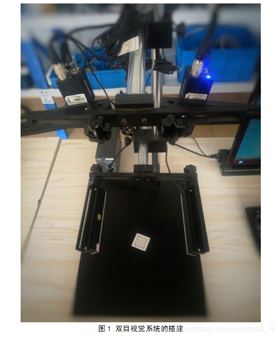
系統搭建如下:

標定程式參考了halcon中的雙目標定示例binocular_calibration.hdev,標定步驟為:
1)程式的初始化設定;
2)建立標定資料模型(也可以不用標定資料模型,下面的程式碼就沒有使用),為相機內參設定初始值;
3)描述標定物件;
4)迴圈讀取多幅影象,提取標定板上的標記點及標定板位姿。
5)執行標定;
*6)進行影象對校正。
程式碼如下:
*
* 該程式演示瞭如何使用 find_caltab, find_marks_and_pose和binocular_calibration 運算元進行雙目立體視覺系統的標定
* 共50幅(左右兩相機分別25幅)。標定完成後,利用對極幾何對影象對進行校正。
*
* ---------------------------------------------------------
* 設定圖片路徑
ImgPath := 'C:/BinocualrCalibration/calibrationImgs/'
* 讀取第一幅影象,並獲取影象尺寸
Index := 1
read_image (ImageL, ImgPath + 'L' + Index$'02d')
read_image (ImageR, ImgPath + 'R' + Index$'02d')
* 開啟合適尺寸大小的視窗
dev_close_window ()
dev_update_off ()
get_image_size (ImageL, WidthL, HeightL)
dev_open_window (0, 0, 0.4*WidthL,0.4* HeightL, 'black', WindowHandle1)
dev_set_draw ('margin')
dev_set_color ('green')
set_display_font (WindowHandle1, 14, 'mono', 'true', 'false')
get_image_size (ImageR, WidthR, HeightR)
dev_open_window (0, 0.4*WidthL + 12, 0.4*WidthL, 0.4*HeightL, 'black', WindowHandle2)
dev_set_draw ('margin')
dev_set_color ('green')
* 讀取標定板模型.
CaltabFile := 'caltab_30mm.descr'
caltab_points (CaltabFile, X, Y, Z)
* 為相機內參設定初始值
StartCamParL := [0.016,0,3.75e-6,3.75e-6,WidthL / 2.0,HeightL / 2.0,WidthL,HeightL]
StartCamParR := StartCamParL
* find_caltab 和 find_marks_and_pose引數設定
SizeGauss := 3
MarkThresh := 120
MinDiamMarks := 5
StartThresh := 128
DeltaThresh := 10
MinThresh := 18
Alpha := 0.9
MinContLength := 15
MaxDiamMarks := 100
* 建立陣列,用於存放影象座標系下的標定點座標和標定板的初始位姿
RowsL := []
ColsL := []
StartPosesL := []
RowsR := []
ColsR := []
StartPosesR := []
*迴圈讀取標定影象
for Index := 1 to 25 by 1
    * 讀取標定影象
    read_image (ImageL, ImgPath + 'L' + Index$'02d')
    read_image (ImageR, ImgPath + 'R' + Index$'02d')
    * 尋找標定板
    find_caltab (ImageL, CaltabL, CaltabFile, SizeGauss, MarkThresh, MinDiamMarks)
    find_caltab (ImageR, CaltabR, CaltabFile, SizeGauss, MarkThresh, MinDiamMarks)
    * 顯示標定板區域
    dev_set_window (WindowHandle1)
    dev_display (ImageL)
    dev_display (CaltabL)
    dev_set_window (WindowHandle2)
    dev_display (ImageR)
    dev_display (CaltabR)
    * (左相機)提取標記點和標定板位姿,並顯示位姿座標
    find_marks_and_pose (ImageL, CaltabL, CaltabFile, StartCamParL, StartThresh, DeltaThresh, MinThresh, Alpha, MinContLength, MaxDiamMarks, RCoordL, CCoordL, StartPoseL)
    disp_caltab (WindowHandle1, CaltabFile, StartCamParL, StartPoseL, 1)
    *(右相機)提取標記點和標定板位姿,並顯示位姿座標
    find_marks_and_pose (ImageR, CaltabR, CaltabFile, StartCamParR, StartThresh, DeltaThresh, MinThresh, Alpha, MinContLength, MaxDiamMarks, RCoordR, CCoordR, StartPoseR)
    disp_caltab (WindowHandle2, CaltabFile, StartCamParR, StartPoseR, 1)
    * 計算標記點在影象座標系下的位姿,並估算所有影象對間的相對位姿
    RowsL := [RowsL,RCoordL]
    ColsL := [ColsL,CCoordL]
    StartPosesL := [StartPosesL,StartPoseL]
    RowsR := [RowsR,RCoordR]
    ColsR := [ColsR,CCoordR]
    StartPosesR := [StartPosesR,StartPoseR]
endfor
*
* 執行標定
*
binocular_calibration (X, Y, Z, RowsL, ColsL, RowsR, ColsR, StartCamParL, StartCamParR, StartPosesL, StartPosesR, 'all', CamParamL, CamParamR, NFinalPoseL, NFinalPoseR, cLPcR, Errors)
* 可以將標定結果存入檔案中:
* write_cam_par (CamParamL, 'cam_left-125.dat')
* write_cam_par (CamParamR, 'cam_right-125.dat')
* write_pose (cLPcR, 'pos_right2left.dat')
* 生成校正的對映圖
gen_binocular_rectification_map (MapL, MapR, CamParamL, CamParamR, cLPcR, 1, 'geometric', 'bilinear', RectCamParL, RectCamParR, CamPoseRectL, CamPoseRectR, RectLPosRectR)
* 讀取已標定系統的一個影象對
read_image (ImageL, ImgPath + 'L01')
read_image (ImageR, ImgPath + 'R01')
* 校正影象對並顯示
map_image (ImageL, MapL, ImageRectifiedL)
map_image (ImageR, MapR, ImageRectifiedR)
* 檢查校正影象的對極約束並顯示結果(包含一些對應的極線)
check_epipolar_constraint (ImageRectifiedL, ImageRectifiedR, RectCamParL, RectCamParR, WindowHandle1, WindowHandle2, CaltabFile, EpipolarError)


三、三維重建
用採集的一對影象對來說明三維立體重建的過程。

三維重建步驟如下:
1)讀取影象對
2)輸入相機引數
3)校正影象對
4)計算視差
5)對視差圖進行處理
6)將視差圖轉換為X、Y、Z分量圖
7)3D點的視覺化
程式碼如下:
* 該程式演示瞭如何使用'disparity_image_to_xyz'運算元。
* 首先進行影象對的校正,然後計算所有視差圖中所有點的 x,y,z 座標,最後將將3D點視覺化。
*
* 初始化設定
dev_close_window ()
dev_update_off ()
dev_set_preferences ('graphics_window_context_menu', 'false')
dev_set_preferences ('suppress_handled_exceptions_dlg', 'true')
*
* 定義要選擇的左右影象對
ImagePath := 'C:/BinocualrCalibration/TestObject/'
Image1 := ImagePath + '/LT08'
Image2 := ImagePath + '/RT08'
*
* 定義相機引數
CamParamL := [0.0162229,-21.9492,3.7503e-006,3.75e-006,622.487,523.778,1280,960]
CamParamR := [0.0160868,-161.835,3.7492e-006,3.75e-006,615.622,514.203,1280,960]
RelPose := [0.13018,-0.000356889,0.0248832,0.434254,343.51,359.836,0]
*
* 生成視差圖
* ******************************************
*
* 生成校正對映影象對
gen_binocular_rectification_map (MapL, MapR, CamParamL, CamParamR, RelPose, 1, 'geometric', 'bilinear', RectCamParL, RectCamParR, CamPoseRectL, CamPoseRectR, RectLPosRectR)
*
* 讀取原影象對並進行校正,得到校正後的影象對
read_image (ImageL, Image1)
read_image (ImageR, Image2)
map_image (ImageL, MapL, ImageRectifiedL)
map_image (ImageR, MapR, ImageRectifiedR)
*
* 顯示校正後的左側影象
get_image_size (ImageRectifiedL, WidthL, HeightL)
dev_open_window (0, 0, 0.4*WidthL,0.4* HeightL, 'black', WindowHandle1)
set_display_font (WindowHandle1, 11, 'mono', 'true', 'false')
dev_display (ImageRectifiedL)
disp_message (WindowHandle1, 'Left rectified image', 'window', 10, 10, 'black', 'true')
*
* 顯示校正後的右側影象
dev_open_window (0, 0.4*WidthL + 10, 0.4*WidthL, 0.4*HeightL, 'black', WindowHandle2)
set_display_font (WindowHandle2, 11, 'mono', 'true', 'false')
dev_display (ImageRectifiedL)
disp_message (WindowHandle2, 'Right rectified image', 'window', 10, 10, 'black', 'true')
disp_continue_message (WindowHandle2, 'black', 'true')
stop ()
*
* 計算視差
binocular_disparity (ImageRectifiedL, ImageRectifiedR, DisparityImage, Score, 'ncc', 33, 33, 0, -36, 20, 1, 0.3, 'left_right_check', 'interpolation')
*
* 填充視差圖中的缺陷
get_domain (DisparityImage, RegionInpainting)
complement (RegionInpainting, RegionInpainting)
full_domain (DisparityImage, DisparityImage)
harmonic_interpolation (DisparityImage, RegionInpainting, DisparityImage, 0.001)
*
* 顯示視差圖
dev_set_window (WindowHandle1)
dev_set_lut ('temperature')
dev_display (DisparityImage)
disp_message (WindowHandle1, 'Disparity image', 'window', 10, 10, 'black', 'true')
*
* 計算點的3D座標
* *******************************************
*
* 將視差圖轉換成X,Y,Z分量圖,分量圖中的灰度值表示各分量的座標
disparity_image_to_xyz (DisparityImage, X, Y, Z, RectCamParL, RectCamParR, RectLPosRectR)
*
* 3D點的視覺化
* *******************************************
*
* 將點雲的中心移至原點附近,並進行z方向上的尺度縮放
min_max_gray (X, X, 5, MinX, MaxX, RangeX)
min_max_gray (Y, Y, 5, MinY, MaxY, RangeY)
min_max_gray (Z, Z, 5, MinZ, MaxZ, RangeZ)
scale_image (X, X, 1.0, -MinX - 0.5 * RangeX)
scale_image (Y, Y, 1.0, -MinY - 0.5 * RangeY)
scale_image (Z, Z, 4.0, -4.0 * MinZ - 2.0 * RangeZ)
*
* 顯示校正後的右影象
dev_set_window (WindowHandle2)
dev_display (ImageRectifiedR)
disp_message (WindowHandle2, 'Computed 3D points in 3D space', 'window', 10, 10, 'black', 'true')
disp_message (WindowHandle2, 'Left button:  rotate', 'window', 205, 10, 'white', 'false')
disp_message (WindowHandle2, 'Right button: exit', 'window', 220, 10, 'white', 'false')
*
* 對3D點雲迴圈旋轉操作的設定
RelQuaternion := [0,0,0,1]
NumAddIn := 0
Cx := WidthL * 0.5
Cy := HeightL * 0.5
*
* 旋轉迴圈
visualize_3D_space (DisparityImage, X, Y, Z, ImageRectifiedL, WindowHandle2, Cx, Cy, HeightL, WidthL, RelQuaternion, NumAddIn, MinX, MinY, MinZ, RangeX, RangeY, RangeZ, RectCamParL)
得到的視差圖如圖3所示,可以看到,目標物體的孔徑周圍有基礎缺陷(白色部分),這是由於在輸入的影象對中,目標物的孔徑周圍反光,顯示為白色,而在計算視差圖時,應儘量避免這種整塊出現的單一顏色區域。


此外,還可以通過建立3D物件模型的方式將結果視覺化。用到的運算元為:xyz_to_object_model_3d( ), create_pose( ), visualize_object_model_3d( )。

注:3D重建的顯示效果和相機標定的精度、拍攝環境、視差圖的演算法等因素相關,其中計算視差圖用到的運算元為binocular_disparity( ),包含的引數較多,需要選擇合適的引數才得到較好的視差圖。
ps:如有錯誤,謝謝指出。整理不易,轉載請註明出處。
