AliOS-Things--ESP8266--Blink--PWM輸出
ESP8266的PWM輸出是基於Blink工程來完成的。 必須的元件:
- ESP8266的PWM庫,路徑為:AliOS-Things-master\AliOS-Things-master\platform\mcu\esp8266\bsp\lib\libpwm.a
使用ESP8266的SDK程式設計方法,偶然調通了!
SDK PWM程式設計
沒有文件,沒有指導,只能從以前寫的ESP8266 SDK PWM程式設計裡面找靈感!如下是我以前寫的PWM輸出例程: 它的效果是,所有的PWM輸出引腳輸出佔空比為0然後慢慢增加到100,佔空比到100之後又緩慢遞減到0的PWM波。迴圈往復。
#include "ets_sys.h" 思考:上面的例程中使用了定時器,但是,在AliOS-Things中完全不知道怎麼用定時器啊!
想起,Blink例程中的LED閃爍那個操作的原理雖然不懂,但是效果和定時器的是一模一樣的!所以,就以Blink例程為基礎進行修改。 因為使用了ESP8266的資源所以需要在Blink.mk裡面新增
NAME := blink

$(NAME)_SOURCES := blink.c

$(NAME)_COMPONENTS += mcu/esp8266   # 新增ESP8266的資源

GLOBAL_DEFINES += AOS_NO_WIFI

$(NAME)_COMPONENTS := yloop cli

GLOBAL_INCLUDES += ./
為啥,是muc/esp8266?因為,mcu的目錄下沒有.mk的檔案,mcu的平級目錄中也沒有.mk檔案,但是mcu目錄下的子目錄esp8266目錄下是有.mk檔案的。根據AliOS-Things的MK規則,現在esp8266下的所有資源都可以使用了。
修改一波之後,如下:
Blink.c
/*
 * Copyright (C) 2015-2017 Alibaba Group Holding Limited
 */

#include <aos/aos.h>
#include <hal/soc/soc.h>
#include "stdio.h"
#include <../../../platform/mcu/esp8266/bsp/include/espressif/pwm.h>
#include <../../../platform/mcu/esp8266/bsp/include/driver/gpio.h>

/**
 * Brief:
 * This test code shows how to configure gpio and how to use gpio interrupt.
 *
 * GPIO status:
 * GPIO18: output
 * GPIO4: output
 * GPIO5:  input, pulled up, interrupt from rising edge and falling edge
 *
 * Test:
 * Connect GPIO18 with LED
 * Connect GPIO4 with GPIO5
 * Generate pulses on GPIO4, that triggers interrupt on GPIO5 to blink the led.
 *
 */

#define GPIO_LED_IO     13
#define GPIO_TRIGGER_IO 4
#define GPIO_INPUT_IO   5
// 暫時只使用0通道的PWM
#define PWM_0_OUT_IO_MUX PERIPHS_IO_MUX_MTDI_U
#define PWM_0_OUT_IO_NUM 12
#define PWM_0_OUT_IO_FUNC FUNC_GPIO12
// #define PWM_1_OUT_IO_MUX PERIPHS_IO_MUX_MTDO_U
// #define PWM_1_OUT_IO_NUM 15
// #define PWM_1_OUT_IO_FUNC FUNC_GPIO15
// #define PWM_2_OUT_IO_MUX PERIPHS_IO_MUX_MTCK_U
// #define PWM_2_OUT_IO_NUM 13
// #define PWM_2_OUT_IO_FUNC FUNC_GPIO13
// #define PWM_3_OUT_IO_MUX PERIPHS_IO_MUX_GPIO4_U
// #define PWM_3_OUT_IO_NUM 4
// #define PWM_3_OUT_IO_FUNC FUNC_GPIO4
// #define PWM_4_OUT_IO_MUX PERIPHS_IO_MUX_GPIO5_U
// #define PWM_4_OUT_IO_NUM 5
// #define PWM_4_OUT_IO_FUNC FUNC_GPIO5
#define PWM_CHANNEL 1   // 只使用了一個通道的PWM

static void app_trigger_low_action(void *arg);
static void app_trigger_high_action(void *arg);

gpio_dev_t led;
gpio_dev_t trigger;
gpio_dev_t input;

static void gpio_isr_handler(void* arg)
{
    uint32_t gpio_num = (uint32_t) arg;
    uint32_t value = 0;
    hal_gpio_input_get(&input, &value);
    hal_gpio_output_toggle(&led);
    LOG("GPIO[%d] intr, val: %d\n", gpio_num, value);
}

/** 呼吸燈執行程式 */
void ESP8266_PWM_RUN( void )
{
    /** PWM佔空比變數 */
    static u8 set_duty = 0;

    /** 佔空比加減標誌 */
    static bool f = true;
    if ( f == true )
    {
        if ( ++set_duty >= 100 )
        {
            f = false;
        }
    }
    else
    {
        if ( --set_duty <= 0 )
        {
            f = true;
        }
    }

    /** 更新PWM通道0的佔空比 */
    printf("set_duty>>>%d\r\n", set_duty);
    pwm_set_duty( set_duty, 0 );
    pwm_start();
}

static void app_trigger_low_action(void *arg)
{
    hal_gpio_output_low(&trigger);
    aos_post_delayed_action(100, app_trigger_high_action, NULL);

    ESP8266_PWM_RUN(); // 放到這裡,如同定時器的效果一樣。
}

static void app_trigger_high_action(void *arg)
{
    hal_gpio_output_high(&trigger);
    aos_post_delayed_action(100, app_trigger_low_action, NULL);
}


/** 初始化PWM配置、系統定時器配置 */
void ESP8266_PWM_Init( void )
{
    struct pwm_param pwm_config_t;

    uint32_t io_info[ ][ 3 ]={
        {PWM_0_OUT_IO_MUX,PWM_0_OUT_IO_FUNC,PWM_0_OUT_IO_NUM},
        // {PWM_1_OUT_IO_MUX,PWM_1_OUT_IO_FUNC,PWM_1_OUT_IO_NUM},
        // {PWM_2_OUT_IO_MUX,PWM_2_OUT_IO_FUNC,PWM_2_OUT_IO_NUM},
        // {PWM_3_OUT_IO_MUX,PWM_3_OUT_IO_FUNC,PWM_3_OUT_IO_NUM},
        // {PWM_4_OUT_IO_MUX,PWM_4_OUT_IO_FUNC,PWM_4_OUT_IO_NUM},
    };

   pwm_config_t.duty[ 0 ] = 0;
   pwm_config_t.freq = 0;
   pwm_config_t.period = 100;

    pwm_init( pwm_config_t.period, pwm_config_t.duty, PWM_CHANNEL, io_info );

    /** 配置定時器每30ms執行一次ESP8266_PWM_RUN()函式 */
    //  os_timer_disarm( &os_timer );
    //  os_timer_setfn( &os_timer, (ETSTimerFunc *) ( ESP8266_PWM_RUN ), NULL );
    //  os_timer_arm( &os_timer, 30, true );
}

int application_start(int argc, char *argv[])
{
    ESP8266_PWM_Init();  // PWM 初始化

    /* gpio port config */
    led.port = GPIO_LED_IO;
    /* set as output mode */
    led.config = OUTPUT_PUSH_PULL;
    /* configure GPIO with the given settings */
    hal_gpio_init(&led);

    /* gpio port config */
    trigger.port = GPIO_TRIGGER_IO;
    /* set as output mode */
    trigger.config = OUTPUT_PUSH_PULL;
    /* configure GPIO with the given settings */
    hal_gpio_init(&trigger);

    /* input pin config */
    input.port = GPIO_INPUT_IO;
    /* set as interrupt mode */
    input.config = IRQ_MODE;
    /* configure GPIO with the given settings */
    hal_gpio_init(&input);

    /* gpio interrupt config */
    hal_gpio_enable_irq(&input, IRQ_TRIGGER_BOTH_EDGES, gpio_isr_handler, (void *) GPIO_INPUT_IO);

    aos_post_delayed_action(1000, app_trigger_low_action, NULL);
    aos_loop_run();

    return 0;
}
報錯:是毫無意外的
1、PERIPHS_IO_MUX_MTDI_U 這個找不到,沒定義(賊多錯誤,滿屏都是)。。。。
解決辦法:在路徑:AliOS-Things-master\AliOS-Things-master\platform\mcu\esp8266\bsp\include\driver\gpio.h這個地方在gpio.h裡面新增如下包含標頭檔案,即可搞定:
#ifndef __GPIO_H__
#define __GPIO_H__

#ifdef __cplusplus
extern "C" {
#endif

/****開始複製****/
#include "c_types.h"
#include "../espressif/esp8266/gpio_register.h"
#include "../espressif/esp8266/pin_mux_register.h"
/*****結束複製****/

#define GPIO_Pin_0              (BIT(0))  /* Pin 0 selected */
編譯:aos make [email protected] 搞定!下載程式之後就可以看到效果了! 注意是引腳是:GPIO12
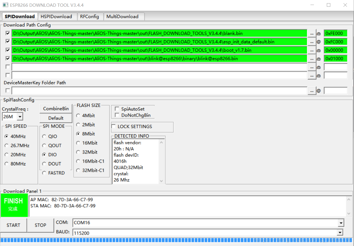
下載程式:
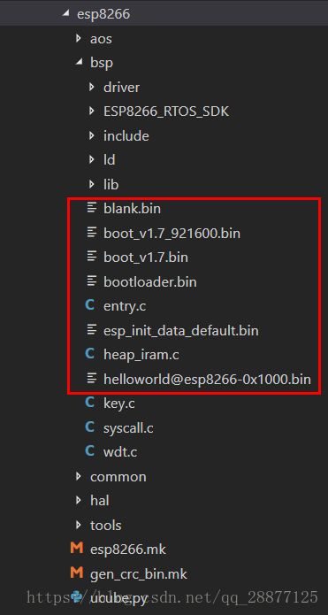
在路徑這裡系統自帶了三個檔案:AliOS-Things-master\AliOS-Things-master\platform\mcu\esp8266,需要同時下載到ESP8266裡面去,具體地址配置下面有截圖。
- blank.bin
- boot_v1.7.bin
- esp_init_data_default.bin
對應地址:
| 檔名 | 下載地址 |
|---|---|
| blank.bin | 0xFE000 |
| esp_init_data_default.bin | 0xFC000 |
| boot_v1.7.bin | 0x00000 |
| [email protected] | 0x01000 |
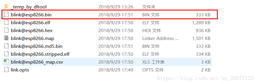
在目錄這裡:AliOS-Things-master\AliOS-Things-master\out\[email protected]\binary有編譯出來的主檔案。