
MuJoCo Tutorial on MIT's Underactuated Robotics in C++
Modelling Inverted Pendulum
Modelling in MuJoCo is done through an XML formatted file called MJCF. According to the documentations, the widely used Unified Robot Description Format (URDF) files are also allowed, but discouraged. Here is the model of a point-mass approximation of inverted pendulum.
Most of the options and flags and stuff are self explanatory. The sites on the ground and beam are there to be connected via tendons, and are reminiscent of the original MJCF that I used, which was modeling something similar to ball and beam. Full disclaimer

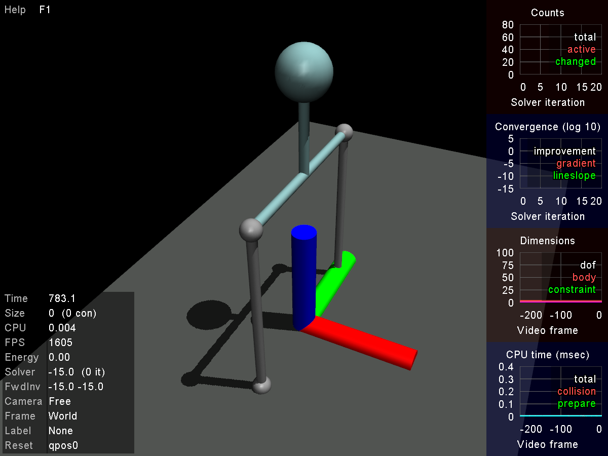
You may not see the RGB frame axis, but it is less relevant here. The following is the main component of the model:
<body name="beam" pos="0 0 .5"> <geom name="rod" type="cylinder" pos="0 0 0.0" size=".01 .1" density="100"/> <geom pos="0 0 -.1" type="capsule" size=".01 .2" euler="1.57 0 0"/> <joint name="pivot" pos="0 0 -0.1" axis="0 1 0" limited="false" damping=".05"/> <site name="rBeam" pos="0 -.2 -.1"/> <site name="lBeam" pos="0 .2 -.1"/> <body name="ballbody" pos="0 0 0.1"> <geom name="ballgeom" type="sphere" size=".05"/> </body></body>
Each joint, e.g. "pivot" adds a degree of freedom between a body and its parent, or worldbody in this case. It is a joint of type hinge which adds a rotational degree of freedom along the y-axis (green), and from this viewpoint, clockwise motion increments the angle. The euler property defines the starting orientation of the geom.
Some geoms and bodies have names, which is discouraged in MuJoCo, because you can load several MJCFs and if some bodies or geoms have exact names, MuJoCo complains about the conflict. But, I think they are useful for a tutorial.
By default, every geom in MuJoCo has the density of water, which is approximately 1000. Thus, I have reduced the density of the rod that connects the ball to the pivot to 100 to better approximate a point-mass formulation.
Finally, I have added a motor actuator, which creates a force at the desired joint, and the angle of that joint will be read by an encoder sensor.
PD Controller
When you are dealing with a real robot, there are a million of things that you should consider. Usually, you have sensors which periodically and most likely asynchronously report their measurements, each of them with nonlinear noise models. Then there’s a control loop that, most likely with a fixed frequency, updates the signal of the controllers using the latest measurements.
These measurements are so unreliable that more often than not, there is the need for some kind of state estimation (my favorite, unscented filter) to get something meaningful out of them. In this module, I will implement the sensor noise and the periodic control loop updates, but I will neglect them in the future modules as they will dilute our control juice.
To install the controller, it’s enough to set your model’s control callback:
mjcb_control = mycontroller;
The function mycontroller will be called whenever you execute mj_step(m,d); but, in order to simulate a control loop, I artificially only periodically update the control signal, which is a simple PD:
if (d->time - last_update > 1.0/ctrl_update_freq){ mjtNum vel = (d->sensordata[0] - position_history)/(d->time-previous_time); ctrl = 3.5*(-vel-10.0*d->sensordata[0]); last_update = d->time; position_history = d->sensordata[0]; previous_time = d->time;}d->ctrl[0] = ctrl;Note that I neglected all about a proper filter to get the velocity right! This is maybe the worst way to estimate velocity, because by taking derivative of a noisy signal, you increase the influence of noise, and if you play a bit with the standard deviation of the sensor noise model in the MJCF file, this controller fails. However, for small values of noise, ta-da:


This simple PD works great, and with a little control engineering intuition (much less than training a neural network ?) you can tune the parameters, simply the velocity coefficient usually controls the oscillation by slowing down your system. In the absence of a disturbance (for example wind, if you are controlling a quadrotor) there is usually no need for an integrator.
This simplicity is a blessing and a curse. It’s great because you don’t even need to know your model! Couple of try and error and it works great. And modeling dynamic systems is difficult. It is not just a matter of buying a ruler! It requires dynamic systems expertise and time-consuming laborious work.
On the other hand, this controller is not taking advantage of the beauties of dynamics. Had I put stricter control limits, it wouldn’t understand to put energy into the system, by applying force to the opposite sign of the state, and do a swing-up.
Unfortunately, our next controller, LQR, is also this dumb ?, but we will reach smarter controllers in no time.
Until then, stay tuned.