
SSD網路解析之PriorBox層
SSD網路中的PriorBox層用於部署特徵圖中每個位置(畫素點)處的預設框(即計算每個預設框相對於網路輸入層輸入影象的歸一化左上角和右下角座標以及設定的座標variance值)
預設框的具體設定,我們需要先看一下原論文中的2.2節部分。
①英文部分如下:
Choosing scales and aspect ratios for default boxes To handle different object scales, some methods [4,9] suggest processing the image at different sizes and combining the results afterwards. However, by utilizing feature maps from several different layers in a single network for prediction we can mimic the same effect, while also sharing parame-ters across all object scales. Previous works [10,11] have shown that using feature maps from the lower layers can improve semantic segmentation quality because the lower layers capture more fine details of the input objects. Similarly, [12] showed that adding global context pooled from a feature map can help smooth the segmentation results.
Motivated by these methods, we use both the lower and upper feature maps for detection. Figure 1 shows two exemplar feature maps (8 × 8 and 4 × 4) which are used in the framework. In practice, we can use many more with small computational overhead.
Feature maps from different levels within a network are known to have different (empirical) receptive field sizes [13]. Fortunately, within the SSD framework, the de-fault boxes do not necessary need to correspond to the actual receptive fields of each layer. We design the tiling of default boxes so that specific feature maps learn to be responsive to particular scales of the objects. Suppose we want to use m feature maps for prediction. The scale of the default boxes for each feature map is computed as:
where is 0.2 and
By combining predictions for all default boxes with different scales and aspect ratios from all locations of many feature maps, we have a diverse set of predictions, covering various input object sizes and shapes. For example, in Fig. 1, the dog is matched to a default box in the 4 × 4 feature map, but not to any default boxes in the 8 × 8 feature map. This is because those boxes have different scales and do not match the dog box, and therefore are considered as negatives during training.
②我翻譯的中文部分如下(中文只是輔助,還是需要從英文入手,才能真正看懂其中的含義):
為預設框選擇尺度和寬高比:為了處理不同的目標尺度,一些方法[4,9]建議處理不同尺寸的影象並在之後組合結果。但是,通過利用單個網路中幾個不同層的特徵圖進行預測,我們可以模擬相同的效果,同時還可以跨所有目標尺度共享引數(即同一個網路實現多尺度目標的處理)。之前的工作[10,11]已經表明,使用較低層的特徵圖可以提高語義分割質量,因為較低層捕獲輸入目標更精細的細節。同樣,[12]表明,從特徵圖中新增全域性上下文可以幫助平滑分割結果。在這些方法的推動下,我們使用低層和高層特徵圖進行檢測。圖1顯示了框架中使用的兩個示例性特徵圖(8×8和4×4)。實際上,我們可以使用更多的小計算開銷(small computational overhead)。
已知網路內不同級別的特徵圖具有不同的(經驗)感受野大小[13]。幸運的是,在SSD框架內,預設框不一定需要與每層的實際感受野相對應。我們設計了預設框的平鋪,以便特定的特徵圖學習響應特定的目標尺度。假設我們想要使用m個特徵圖進行預測。每個特徵圖的預設框的尺寸計算如下:
其中, 取為0.2,
取為0.9,表示最低層的尺度為0.2,最高層的尺度為0.9,其間的所有層都是規則間隔的。我們對預設框施加不同的寬高比,記為
。由此能夠計算每一個預設框的寬度(
)和高度(
)。對於寬高比為1時,我們還添加了一個預設框,其尺寸為
,由此在每個特徵圖位置處產生6個預設框。我們設定每個預設框的中心為
,其中
表示第k個方形特徵圖的大小(即特徵圖的長/寬),
。在實踐中,還可以設計預設框的分佈以最佳地適合特定資料集。 如何設計最佳平鋪也是一個懸而未決的問題(開放性問題)。
通過結合來自多個特徵圖的所有位置的具有不同尺寸和寬高比的所有預設框的預測,我們具有多種預測,涵蓋各種輸入目標尺寸和形狀。例如,在圖1中,狗匹配4×4特徵圖中的預設框,但不匹配8×8特徵圖中的任何預設框。這是因為這些框具有不同的尺寸並與狗框不匹配,因此在訓練期間被認為是負例。
其中的圖1如下:
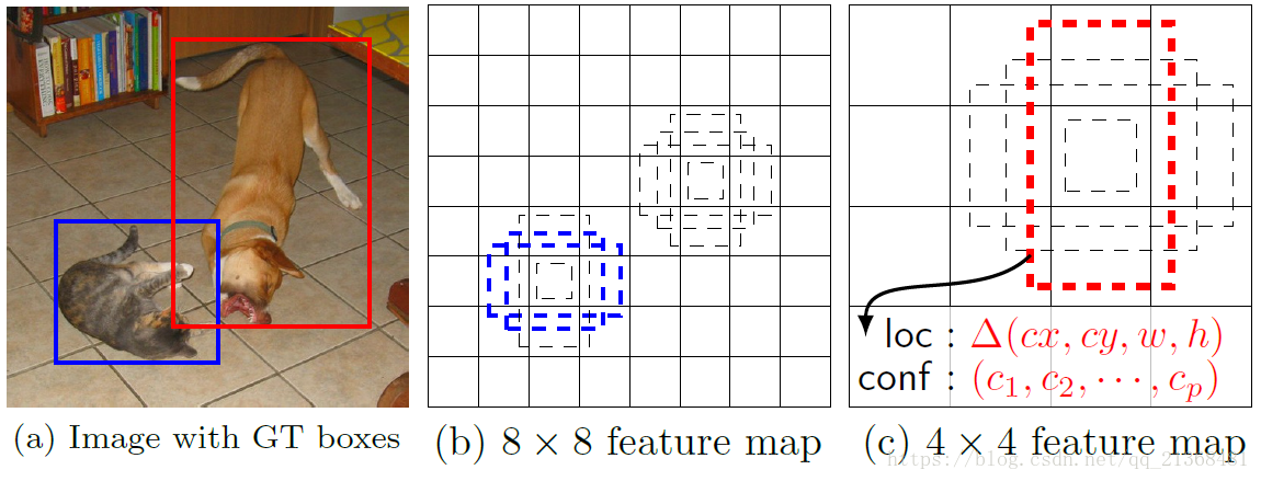
圖 1 SSD框架。(a)SSD在訓練期間僅需要每個物件的輸入影象和地面實況框。以卷積方式,我們在幾個具有不同形狀尺寸的特徵圖(例如,8×8 和4×4 在(b)和(c)中)中的每個位置處評估一組不同寬高比的小集(例如4個)。對於每個預設框,我們預測形狀偏移和所有目標類別的置信度()。在訓練時,我們首先將這些預設框與地面實況框匹配。例如,我們將兩個預設框一個與cat匹配,一個與dog匹配,它們被視為正例,其餘的為負例(即與地面實況框匹配上的為正例,否則為負例)。模型損失是定位損失(例如,smooth L1 [6])和置信度損失(例如,Softmax)之間的加權和
從中我們可以看出,在特徵圖的每個位置(畫素點)處都會有幾個設定的預設框(4-6個),這些預設框的寬高比是需要我們設定的,而不同層上的特徵圖上的預設框的寬度和高度是根據和
所確定的。
注:同一層的所有特徵圖共享一組預設框。
(1)caffe.proto中關於該層引數的說明
該層所需要設定的引數比較多:
// Message that store parameters used by PriorBoxLayer
message PriorBoxParameter {
  // Encode/decode type.
  enum CodeType {
    CORNER = 1;
    CENTER_SIZE = 2;
    CORNER_SIZE = 3;
  }
  // Minimum box size (in pixels). Required!
  repeated float min_size = 1; //對應論文2.2節中公式(4)中的sk×網路輸入層輸入影象[data層的輸入]大小
  // Maximum box size (in pixels). Required!
  repeated float max_size = 2; //下一層用來生成預設框特徵圖所在的min_size(對應論文2.2節中公式(4)中的sk+1×網路輸入層輸入影象[data層的輸入]大小)
  // Various of aspect ratios. Duplicate ratios will be ignored.
  // If none is provided, we use default ratio 1.
  repeated float aspect_ratio = 3; //寬高比
  // If true, will flip each aspect ratio.
  // For example, if there is aspect ratio "r",
  // we will generate aspect ratio "1.0/r" as well.
  optional bool flip = 4 [default = true]; //是否翻轉寬高比
  // If true, will clip the prior so that it is within [0, 1]
  optional bool clip = 5 [default = false]; //是否進行裁剪(是否保證預設框整個在網路輸入層輸入影象內)
  // Variance for adjusting the prior bboxes.
  repeated float variance = 6; //暫時未知用來做什麼
  // By default, we calculate img_height, img_width, step_x, step_y based on
  // bottom[0] (feat) and bottom[1] (img). Unless these values are explicitely
  // provided.
  // Explicitly provide the img_size.
  optional uint32 img_size = 7;
  // Either img_size or img_h/img_w should be specified; not both.
  optional uint32 img_h = 8; //網路輸入層輸入影象的高(或自行設定的高度)
  optional uint32 img_w = 9; //網路輸入層輸入影象的寬(或自行設定的寬度)

  // Explicitly provide the step size.
  optional float step = 10;
  // Either step or step_h/step_w should be specified; not both.
  optional float step_h = 11; //特徵圖上同一列上相鄰兩畫素點間的距離在網路輸入層輸入影象上的距離
  optional float step_w = 12; //特徵圖上同一行上相鄰兩畫素點間的距離在網路輸入層輸入影象上的距離

  // Offset to the top left corner of each cell.
  optional float offset = 13 [default = 0.5]; //預設框中心偏移量(相對偏移量)
}
其中幾個重要的引數說明如下:
min_size:該層的乘上網路輸入層的輸入影象大小(data層),即是一個畫素值
max_size:下一層的(即論文中的
)乘上網路輸入層的輸入影象大小(data層),即是一個畫素值
注:min_size和max_size是用來計算額外新增的寬高比為1時的一個預設框的引數(即為了計算其尺寸)
step/step_h,step_w:用於計算當前特徵圖上某一位置處所有預設框中心座標在網路輸入層輸入影象座標系下的座標
由此我們可以先提前看一下該層在train.prototxt(SSD300的訓練網路)中的樣子:
layer {
  name: "conv4_3_norm_mbox_priorbox"
  type: "PriorBox"
  bottom: "conv4_3_norm"
  bottom: "data"
  top: "conv4_3_norm_mbox_priorbox"
  prior_box_param {
    min_size: 30.0
    max_size: 60.0
    aspect_ratio: 2
    flip: true
    clip: false
    variance: 0.1
    variance: 0.1
    variance: 0.2
    variance: 0.2
    step: 8
    offset: 0.5
  }
}
拿上面的conv4_3層的特徵圖為例,從中可以看出該層需要有兩個輸入,即bottom[0]為上面的conv4_3_norm,bottom[1]為上面的data(也即網路輸入層輸入影象)。
①min_size和max_size進一步分析
SSD300網路(300即輸入影象大小為300×300)修改自VGG16網路,大家可以自行推導一下conv4_3層特徵圖的大小(我推出來是38×38,注意caffe中的卷積層是向下取整的,即用floor函式來計算最終的特徵圖大小;而池化層是向上取整的,即用cell函式來計算特徵圖大小,大家不信的話可以去原始碼中找一下)。
這裡的min_size,max_size在SSD300中並不完全遵循2.2節部分中的公式,但所表示的意思即是
和
,原因在論文後面說了(對於conv4_3採用的
),如下圖:

為何說沒遵守這一公式呢,從網路整體,我們可以提取出所有的min_size和max_size如下表:
| 層名稱 | 特徵圖大小( |
min_size | max_size | step |
| conv4_3 | 38*38 | 30 | 60 | 8 |
| fc7 | 19*19 | 60 | 111 | 16 |
| conv6_2 | 10*10 | 111 | 162 | 32 |
| conv7_2 | 5*5 | 162 | 213 | 64 |
| conv8_2 | 3*3 | 213 | 264 | 100 |
| conv9_2 | 1*1 | 264 | 315 | 300 |
從表中可以看出,
,
,
,
,
,
,故並不遵循上述公式(conv4_3層是設定好為0.1的)。
當然,如果我們不看conv4_3層,只看fc7-conv9_2層,是遵循上述公式的,即(大家可以自行帶進去算算)。
②step引數分析
step引數本質上是該層的特徵圖相對於網路輸入層輸入影象的下采樣率,用於計算當前特徵圖上某一位置處所有預設框中心座標在網路輸入層輸入影象座標系下的座標。舉個例子,就是你在縮放一幅影象時,對於縮放後的影象,其上每一畫素點的畫素值是通過插值得到的,那如何有效插值就需要用到後向計算,即需要找出當前畫素點座標值對應於原始影象上的座標值,由原始影象上這一座標值來最鄰近或雙線性插值,重點就在於需要找出原始影象上的座標值。而這裡的step就是用來計算特徵圖上某一位置處所有預設框中心座標在網路輸入層輸入影象座標系下的座標,對應的就是下采樣率,拿conv4_3而言,下采樣率為38/300約為8(實際上就是8,因為經過三次最大池化操作,但由於caffe中的池化採用向上取整,導致約等於8),故step=8,其餘層大家可以自行計算一下(不要過於糾結準確下采樣率,大致就行,畢竟最後都是要通過網路自行學習的,沒必要那麼精確),當然大家要是還是不理解的話,請參考後面cpp檔案中的Forward_cpu函式的實現來加深理解。
注:,其中
為網路輸入層輸入影象大小。
(2)標頭檔案prior_box_layer.hpp
該層所需要的函式和變數均定義在prior_box_layer.hpp檔案中:
#ifndef CAFFE_PRIORBOX_LAYER_HPP_
#define CAFFE_PRIORBOX_LAYER_HPP_

#include <vector>

#include "caffe/blob.hpp"
#include "caffe/layer.hpp"
#include "caffe/proto/caffe.pb.h"

namespace caffe {

/**
 * @brief Generate the prior boxes of designated sizes and aspect ratios across
 *        all dimensions @f$ (H \times W) @f$.
 *
 * Intended for use with MultiBox detection method to generate prior (template).
 *
 * NOTE: does not implement Backwards operation.
 */
template <typename Dtype>
class PriorBoxLayer : public Layer<Dtype> {
 public:
  /**
   * @param param provides PriorBoxParameter prior_box_param,
   *     with PriorBoxLayer options:
   *   - min_size (\b minimum box size in pixels. can be multiple. required!). 對應論文2.2節中公式(4)中的sk×網路輸入層輸入影象[data層的輸入]大小
   *   - max_size (\b maximum box size in pixels. can be ignored or same as the 對應論文2.2節中公式(4)中的sk+1×網路輸入層輸入影象[data層的輸入]大小
   *   # of min_size.).
   *   - aspect_ratio (\b optional aspect ratios of the boxes. can be multiple).
   *   - flip (\b optional bool, default true).
   *     if set, flip the aspect ratio.
   */
  explicit PriorBoxLayer(const LayerParameter& param)
      : Layer<Dtype>(param) {}
  virtual void LayerSetUp(const vector<Blob<Dtype>*>& bottom,
      const vector<Blob<Dtype>*>& top);
  virtual void Reshape(const vector<Blob<Dtype>*>& bottom,
      const vector<Blob<Dtype>*>& top);

  virtual inline const char* type() const { return "PriorBox"; }
  virtual inline int ExactBottomBlobs() const { return 2; } //輸入blob數目為2(第一個blob一般為特徵圖;第二個blob一般為data層輸入的影象)
  virtual inline int ExactNumTopBlobs() const { return 1; } //輸出blob數目為1

 protected:
  /**
   * @brief Generates prior boxes for a layer with specified parameters.
   *
   * @param bottom input Blob vector (at least 2)
   *   -# @f$ (N \times C \times H_i \times W_i) @f$
   *      the input layer @f$ x_i @f$
   *   -# @f$ (N \times C \times H_0 \times W_0) @f$
   *      the data layer @f$ x_0 @f$
   * @param top output Blob vector (length 1)
   *   -# @f$ (N \times 2 \times K*4) @f$ where @f$ K @f$ is the prior numbers
   *   By default, a box of aspect ratio 1 and min_size and a box of aspect
   *   ratio 1 and sqrt(min_size * max_size) are created.
   */
  //前向傳播實質是計算各預設框引數(左上角和右下角歸一化座標+座標variance)
  virtual void Forward_cpu(const vector<Blob<Dtype>*>& bottom,
      const vector<Blob<Dtype>*>& top);
  /// @brief Not implemented 無需後向傳播
  virtual void Backward_cpu(const vector<Blob<Dtype>*>& top,
      const vector<bool>& propagate_down, const vector<Blob<Dtype>*>& bottom) {
    return;
  }

  vector<float> min_sizes_;  //儲存所設定的min_size(對應論文2.2節中公式(4)中的sk×網路輸入層輸入影象大小)
  vector<float> max_sizes_;  //下一層用來生成預設框特徵圖所在的min_size(對應論文2.2節中公式(4)中的sk+1×網路輸入層輸入影象大小)
  vector<float> aspect_ratios_; //儲存所設定的寬高比(包含預設的寬高比1)
  bool flip_; //是否翻轉寬高比
  int num_priors_;  //預設框數目(default box)
  bool clip_; //是否進行裁剪(是否保證預設框整個在網路輸入層輸入影象內)
  vector<float> variance_; //儲存variance(暫時不清楚此引數用來做什麼)

  int img_w_; //網路輸入層輸入影象的寬(或自行設定的寬度)
  int img_h_; //網路輸入層輸入影象的高(或自行設定的高度)
  float step_w_; //特徵圖上同一行上相鄰兩畫素點間的距離在網路輸入層輸入影象上的距離
  float step_h_; //特徵圖上同一列上相鄰兩畫素點間的距離在網路輸入層輸入影象上的距離

  float offset_; //預設框中心偏移量(相對偏移量)
};

}  // namespace caffe

#endif  // CAFFE_PRIORBOX_LAYER_HPP_
(3)prior_box_layer.cpp檔案
所定義的函式在prior_box_layer.cpp檔案中實現(只實現了CPU版本,無需GPU版本),需要注意的是後向傳播(Backward_cpu)函式無需實現,因為該層只是為了建立各預設框,儲存各預設框的引數,且這些引數無需更新,也即無需進行後向傳播。
#include <algorithm>
#include <functional>
#include <utility>
#include <vector>

#include "caffe/layers/prior_box_layer.hpp"

namespace caffe {

//建立PriorBox層
template <typename Dtype>
void PriorBoxLayer<Dtype>::LayerSetUp(const vector<Blob<Dtype>*>& bottom,
      const vector<Blob<Dtype>*>& top) {
  const PriorBoxParameter& prior_box_param =
      this->layer_param_.prior_box_param();  //獲取所需的引數
  CHECK_GT(prior_box_param.min_size_size(), 0) << "must provide min_size."; //min_size是必須的,不可預設設定
  for (int i = 0; i < prior_box_param.min_size_size(); ++i) {
    min_sizes_.push_back(prior_box_param.min_size(i));
    CHECK_GT(min_sizes_.back(), 0) << "min_size must be positive."; //min_size必須為正數(CHECK_GT表示大於[greater than])
  }
  aspect_ratios_.clear();
  aspect_ratios_.push_back(1.);  //預設情況下寬高比為1(也即會預設設定一個為1的寬高比)
  flip_ = prior_box_param.flip(); //flip=true表示翻轉寬高比,即原設定的寬高比為2,則翻轉後寬高比為1/2
  //篩選不同的寬高比(即允許設定的寬高比重複,程式碼會自動找出不重複的,也即不同的寬高比)
  for (int i = 0; i < prior_box_param.aspect_ratio_size(); ++i) {
    float ar = prior_box_param.aspect_ratio(i);
    bool already_exist = false;
    for (int j = 0; j < aspect_ratios_.size(); ++j) {
      if (fabs(ar - aspect_ratios_[j]) < 1e-6) {
        already_exist = true;
        break; //跳出當前for迴圈
      }
    }
    if (!already_exist) {
      aspect_ratios_.push_back(ar); //將不同的寬高比放入aspect_ratios_中
      if (flip_) {
        aspect_ratios_.push_back(1./ar); //將翻轉後的寬高比也放入aspect_ratios_中
      }
    }
  }
  num_priors_ = aspect_ratios_.size() * min_sizes_.size(); //計算需要生成的預設框(參見論文中的default box術語)數目
  if (prior_box_param.max_size_size() > 0) {
    CHECK_EQ(prior_box_param.min_size_size(), prior_box_param.max_size_size()); //檢查所設定的min_size數目和max_size數目是否相等(CHECK_EQ表示相等)
    for (int i = 0; i < prior_box_param.max_size_size(); ++i) {
      max_sizes_.push_back(prior_box_param.max_size(i));
      CHECK_GT(max_sizes_[i], min_sizes_[i])
          << "max_size must be greater than min_size."; //max_size必須大於min_size
      num_priors_ += 1;  //預設框數目加1
    }
  }
  clip_ = prior_box_param.clip();  //獲取裁剪引數
  //獲取variance引數(使用者可設定1個或4個或不設定)
  if (prior_box_param.variance_size() > 1) {
    // Must and only provide 4 variance. 此情況下有且只能設定4個variance
    CHECK_EQ(prior_box_param.variance_size(), 4);
    for (int i = 0; i < prior_box_param.variance_size(); ++i) {
      CHECK_GT(prior_box_param.variance(i), 0);
      variance_.push_back(prior_box_param.variance(i));
    }
  } else if (prior_box_param.variance_size() == 1) { //此情況下表示只設置一個variance
    CHECK_GT(prior_box_param.variance(0), 0);
    variance_.push_back(prior_box_param.variance(0));
  } else {
    // Set default to 0.1.
    variance_.push_back(0.1); //預設情況下設定variance = 0.1
  }

  if (prior_box_param.has_img_h() || prior_box_param.has_img_w()) {
    CHECK(!prior_box_param.has_img_size())
        << "Either img_size or img_h/img_w should be specified; not both."; //兩者只能設定一種
    img_h_ = prior_box_param.img_h();
    CHECK_GT(img_h_, 0) << "img_h should be larger than 0.";
    img_w_ = prior_box_param.img_w();
    CHECK_GT(img_w_, 0) << "img_w should be larger than 0.";
  } else if (prior_box_param.has_img_size()) {
    const int img_size = prior_box_param.img_size();
    CHECK_GT(img_size, 0) << "img_size should be larger than 0.";
    img_h_ = img_size;
    img_w_ = img_size;
  } else {
    img_h_ = 0;  //如果兩者均未設定,則先賦值為0
    img_w_ = 0;
  }
  //同上
  if (prior_box_param.has_step_h() || prior_box_param.has_step_w()) {
    CHECK(!prior_box_param.has_step())
        << "Either step or step_h/step_w should be specified; not both.";
    step_h_ = prior_box_param.step_h();
    CHECK_GT(step_h_, 0.) << "step_h should be larger than 0.";
    step_w_ = prior_box_param.step_w();
    CHECK_GT(step_w_, 0.) << "step_w should be larger than 0.";
  } else if (prior_box_param.has_step()) {
    const float step = prior_box_param.step();
    CHECK_GT(step, 0) << "step should be larger than 0.";
    step_h_ = step;
    step_w_ = step;
  } else {
    step_h_ = 0;
    step_w_ = 0;
  }

  offset_ = prior_box_param.offset();  //獲取相對左上角的偏移量(預設為0.5)
}

//設定輸出blob的大小
template <typename Dtype>
void PriorBoxLayer<Dtype>::Reshape(const vector<Blob<Dtype>*>& bottom,
      const vector<Blob<Dtype>*>& top) {
  //獲取特徵圖的長和寬
  const int layer_width = bottom[0]->width();
  const int layer_height = bottom[0]->height();
  vector<int> top_shape(3, 1);
  // Since all images in a batch has same height and width, we only need to
  // generate one set of priors which can be shared across all images.
  top_shape[0] = 1; //由於每一batch中所有特徵圖具有相同的長和寬,因此我們只需要生成一組可以在該batch中所有特徵圖之間共享的預設框
  // 2 channels. First channel stores the mean of each prior coordinate.
  // Second channel stores the variance of each prior coordinate.
  top_shape[1] = 2; //第一個通道儲存預設框左上角和右下角歸一化座標;第二個通道儲存這些座標的variance
  top_shape[2] = layer_width * layer_height * num_priors_ * 4; //特徵圖每一畫素點處都產生num_priors_個預設框,每個預測框相對預設框有4歸一化座標值/也有4個variance
  CHECK_GT(top_shape[2], 0);
  top[0]->Reshape(top_shape);
}

//前向傳播(實質是計算每個預設框的引數資訊)
template <typename Dtype>
void PriorBoxLayer<Dtype>::Forward_cpu(const vector<Blob<Dtype>*>& bottom,
    const vector<Blob<Dtype>*>& top) {
  const int layer_width = bottom[0]->width();  //bottom[0]一般為特徵圖(feature map);bottom[1]一般為網路輸入層輸入資料即data
  const int layer_height = bottom[0]->height();
  int img_width, img_height;
  if (img_h_ == 0 || img_w_ == 0) {
    img_width = bottom[1]->width();
    img_height = bottom[1]->height();
  } else {
    img_width = img_w_;
    img_height = img_h_;
  }
  float step_w, step_h;
  if (step_w_ == 0 || step_h_ == 0) {
    step_w = static_cast<float>(img_width) / layer_width;
    step_h = static_cast<float>(img_height) / layer_height;
  } else {
    step_w = step_w_;
    step_h = step_h_;
  }
  Dtype* top_data = top[0]->mutable_cpu_data();
  int dim = layer_height * layer_width * num_priors_ * 4;
  int idx = 0;

  //巢狀for迴圈來設定預設框資料(參見論文2.2節Choosing scales and aspect ratios for default boxes部分)
  for (int h = 0; h < layer_height; ++h) {
    for (int w = 0; w < layer_width; ++w) {
      float center_x = (w + offset_) * step_w;  //預設框中心在網路輸入層輸入影象(即網路的data層輸入影象)上的x座標
      float center_y = (h + offset_) * step_h; //預設框中心在網路輸入層輸入影象上的y座標
      float box_width, box_height;
      for (int s = 0; s < min_sizes_.size(); ++s) {
        int min_size_ = min_sizes_[s];
        // first prior: aspect_ratio = 1, size = min_size
        box_width = box_height = min_size_;
        // xmin
        top_data[idx++] = (center_x - box_width / 2.) / img_width;  //預設框左上角歸一化後x座標(歸一化後,即網路輸入層輸入影象x座標在0-1範圍內)
        // ymin
        top_data[idx++] = (center_y - box_height / 2.) / img_height; //預設框左上角歸一化後y座標
        // xmax
        top_data[idx++] = (center_x + box_width / 2.) / img_width; //預設框右下角歸一化後x座標
        // ymax
        top_data[idx++] = (center_y + box_height / 2.) / img_height; //預設框右下角歸一化後y座標

        if (max_sizes_.size() > 0) {
          CHECK_EQ(min_sizes_.size(), max_sizes_.size());
          int max_size_ = max_sizes_[s];
          // second prior: aspect_ratio = 1, size = sqrt(min_size * max_size) 論文中額外新增的另一個寬高比為1的預設框
          box_width = box_height = sqrt(min_size_ * max_size_);
          // xmin
          top_data[idx++] = (center_x - box_width / 2.) / img_width;
          // ymin
          top_data[idx++] = (center_y - box_height / 2.) / img_height;
          // xmax
          top_data[idx++] = (center_x + box_width / 2.) / img_width;
          // ymax
          top_data[idx++] = (center_y + box_height / 2.) / img_height;
        }

        // rest of priors 計算剩餘的預設框左上角和右下角座標
        for (int r = 0; r < aspect_ratios_.size(); ++r) {
          float ar = aspect_ratios_[r];
          if (fabs(ar - 1.) < 1e-6) { //除去寬高比為1的情況,上面已經計算了
            continue;
          }
          box_width = min_size_ * sqrt(ar);
          box_height = min_size_ / sqrt(ar);
          // xmin
          top_data[idx++] = (center_x - box_width / 2.) / img_width;
          // ymin
          top_data[idx++] = (center_y - box_height / 2.) / img_height;
          // xmax
          top_data[idx++] = (center_x + box_width / 2.) / img_width;
          // ymax
          top_data[idx++] = (center_y + box_height / 2.) / img_height;
        }
      }
    }
  }
  // clip the prior's coordidate such that it is within [0, 1]
  //如果clip=true,表示要保證預設框的左上角座標和右下角座標(歸一化後)均需要在原影象內
  if (clip_) {
    for (int d = 0; d < dim; ++d) {
      top_data[d] = std::min<Dtype>(std::max<Dtype>(top_data[d], 0.), 1.);
    }
  }
  // set the variance.設定variance(暫時還不知道此部分用來做什麼)
  top_data += top[0]->offset(0, 1);
  if (variance_.size() == 1) {
    caffe_set<Dtype>(dim, Dtype(variance_[0]), top_data);
  } else {
    int count = 0;
    for (int h = 0; h < layer_height; ++h) {
      for (int w = 0; w < layer_width; ++w) {
        for (int i = 0; i < num_priors_; ++i) {
          for (int j = 0; j < 4; ++j) {
            top_data[count] = variance_[j];
            ++count;
          }
        }
      }
    }
  }
}

INSTANTIATE_CLASS(PriorBoxLayer);
REGISTER_LAYER_CLASS(PriorBox);

}  // namespace caffe
(4)圖示加深理解
較為傳統的方法如下圖(可以自行學習一下Ng的deep learning.ai的第四門課的第三週):
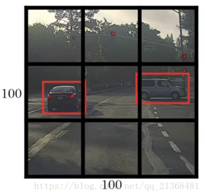
圖中黑色的框即是我們事先設定的預設框,紅色的框為地面實況框。
採用卷積實現視窗滑動,並通過網路自行學習來輸出精確邊界框,設定標籤為一個向量,包括是否存在目標、邊框中心座標、邊框寬高、目標類別等,然後通過卷積神經網路進行學習,得到較佳的預測
。

其中如何定義邊框中心座標、邊框寬高呢,一種方法如下:
可以定義相對邊框中心座標和邊框寬高,例如對於右邊的車,預設框(事先定義的框,黑色)左上角座標為(0,0),右下角座標為(1,1),由此得到標籤中的地面實況框的中心座標約為(0.4,0.3),即,而寬高為
。
而SSD的做法更為高明,是直接在特徵圖上設定一系列預設框,這些預設框的引數,即左上角座標和右下角座標(不採用中心座標和長寬形式)是經過歸一化的,即是相對於網路輸入層輸入影象座標系下的座標(輸入影象左上角定義為(0,0),右下角定義為(1,1),由此建立起輸入影象座標系),這樣之後學習出的引數即是相對於輸入影象座標系而言的。另一個高明之處在於,所設定的預設框寬高比是多樣的,特徵圖尺寸也是多樣的(不同層的特徵圖尺寸不同,也即下采樣率不同,也就導致預設框在輸入影象上所佔的面積不同),不像上圖中的黑色預設框是固定的,這樣做能更加適合現實中同一目標在不同時刻不同地點具有不同尺寸,即提高檢測多尺度目標的效果。
如需轉載,請標明出處!