Linux 裝置驅動篇之I2c裝置驅動
Linux 裝置驅動篇之I2c裝置驅動
fulinux
一、I2C驅動體系
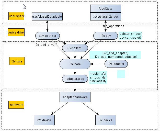
雖然I2C硬體體系結構和協議都很容易理解,但是Linux I2C驅動體系結構卻有相當的複雜度,它主要由3部分組成,即I2C裝置驅動、I2C匯流排驅動和I2C核心。
1.I2C核心
I2C核心是I2c匯流排和I2c裝置驅動的中間樞紐,它以通用的、與平臺無關的介面實現了I2C中裝置與介面卡的溝通,提供了I2C匯流排驅動和裝置驅動的註冊、登出方法,I2C通訊方法(即“algorithm”)上層的、與具體介面卡無關的程式碼以及探測裝置、檢測裝置的地址的上層程式碼等。I2c匯流排驅動填充I2c_adapter和I2c_algorithm結構體,
2.I2C匯流排驅動
I2C匯流排驅動是對I2C硬體體系結構中介面卡的實現,介面卡可由CPU控制,甚至可以直接整合在CPU內部。
I2C匯流排驅動主要包含了I2C介面卡資料結構i2c_adapter、I2C介面卡的algorithm資料結構i2c_algorithm和控制I2C介面卡產生通訊訊號的函式。
經由I2C匯流排驅動的程式碼,我們可以控制I2C介面卡以主控制方式產生開始、停止位、讀寫週期,以及以從裝置方式讀寫、產生ACK等。
3.I2C裝置驅動
I2C裝置驅動(也稱為客戶端驅動)是對I2C硬體體系結構中裝置端的實現,裝置一般掛接在受
I2C裝置驅動主要包含了資料結構體i2c_driver和i2c_client,我們需要具體裝置實現其中的成員函式。
圖1 I2C驅動體系結構圖1
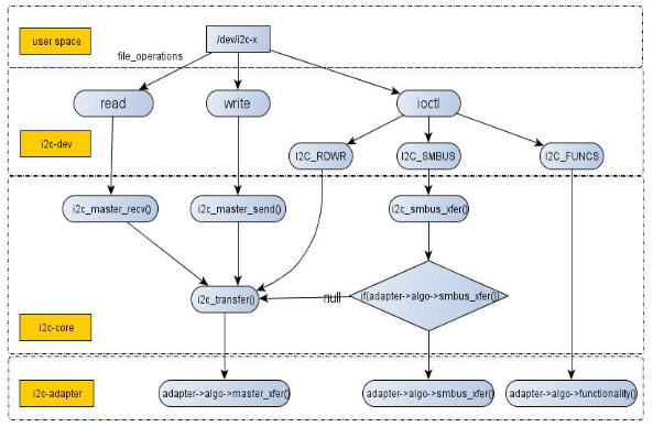
圖2 I2C驅動體系結構圖2
另外,系統中i2c-dev.c檔案定義的主裝置號為89的裝置可以方便地給應用程式提供讀寫I2c裝置暫存器的能力,使得工程師大多數時候並不需要為具體的I2c裝置驅動定義檔案操作介面。
如何理解adapter和client呢?它在s3c2440中對應的是什麼?Adapter和client都是linux驅動軟體抽象出來的東西,Linux I2C框架搞那麼複雜是為了通用性及為了符合
在linux核心中,所有的I2C裝置都在sysfs檔案系統中顯示,存在於/sys/bus/i2c/目錄下,介面卡地址和晶片地址的形式列出,例如:
1. [[email protected] linux-3.0]$ tree /sys/bus/i2c/
2. /sys/bus/i2c/
3. |-- devices
4. | |-- i2c-0 -> ../../../devices/pci0000:00/0000:00:02.0/i2c-0
5. | |-- i2c-1 -> ../../../devices/pci0000:00/0000:00:02.0/i2c-1
6. | |-- i2c-2 -> ../../../devices/pci0000:00/0000:00:02.0/i2c-2
7. | |-- i2c-3 -> ../../../devices/pci0000:00/0000:00:02.0/i2c-3
8. | |-- i2c-4 -> ../../../devices/pci0000:00/0000:00:02.0/i2c-4
9. | |-- i2c-5 -> ../../../devices/pci0000:00/0000:00:02.0/i2c-5
10. | |-- i2c-6 -> ../../../devices/pci0000:00/0000:00:02.0/drm/card0/card0-DP-1/i2c-6
11. | `-- i2c-7 -> ../../../devices/pci0000:00/0000:00:02.0/drm/card0/card0-DP-2/i2c-7
12. |-- drivers
13. | |-- 88PM860x
14. | | |-- bind
15. | | |-- uevent
16. | | `-- unbind
17. | |-- aat2870
18. | | |-- bind
19. | | |-- uevent
20. | | `-- unbind
21. | |-- ab3100
22. | | |-- bind
23. | | |-- uevent
24. | | `-- unbind
25. | |-- adp5520
下面我以s3c2440開發板及其之上的EEPROM晶片AT24C02和linux-3.0核心平臺講解I2c的三個部分。
********************************************************************************************
轉載宣告:希望大家能轉載此文謝謝 原文連結
********************************************************************************************
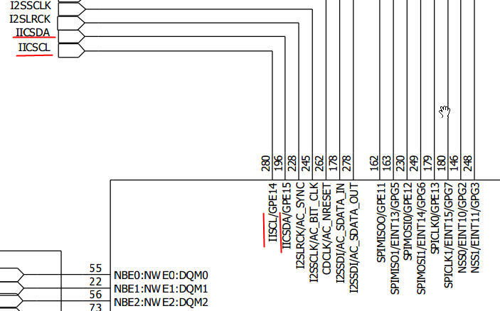
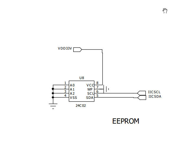
4.s3c2440和at24c02硬體特性
請看s3c2440.pdf
晶片AT24C02的電氣特性:
• Low-voltage and Standard-voltage Operation
– 2.7 (VCC= 2.7V to 5.5V)
– 1.8 (VCC= 1.8V to 5.5V)
• Internally Organized 128 x 8 (1K), 256 x 8 (2K), 512 x 8 (4K),
1024 x 8 (8K) or 2048 x 8 (16K)
• Two-wire Serial Interface
• Schmitt Trigger, Filtered Inputs for Noise Suppression
• Bidirectional Data Transfer Protocol
• 100 kHz (1.8V) and 400 kHz (2.7V, 5V) Compatibility
• Write Protect Pin for Hardware Data Protection
• 8-byte Page (1K, 2K), 16-byte Page (4K, 8K, 16K) Write Modes
• Partial Page Writes Allowed
• Self-timed Write Cycle (5 ms max)
• High-reliability
– Endurance: 1 Million Write Cycles
– Data Retention: 100 Years
• Automotive Grade and Lead-free/Halogen-free Devices Available
• 8-lead PDIP, 8-lead JEDEC SOIC, 8-lead MAP, 5-lead SOT23,
8-lead TSSOP and 8-ball dBGA2 Packages
• Die Sales: Wafer Form, Waffle Pack and Bumped Wafers
主要是看AT24C02.pdf
圖3 S3c244開發板核心板電路圖
圖4 AT24C02電路圖
5.i2c.h標頭檔案
核心中i2c.h這個標頭檔案對i2c_driver、i2c_client、i2c_adapter和i2c_algorithm著4個數據結構進行了定義。理解這4個結構的作用十分關鍵,程式碼清單1、2、3、4分別給出了它們的定義。
程式碼清單1 i2c_adapter結構體
1. /*
2. * i2c_adapter is the structure used to identify a physical i2c bus along
3. * with the access algorithms necessary to access it.
4. */
5. struct i2c_adapter {
6. struct module *owner;
7. unsigned int class; /* classes to allow probing for */
8. const struct i2c_algorithm *algo; /* the algorithm to access the bus */
9. void *algo_data;
10. /* data fields that are valid for all devices */
11. struct rt_mutex bus_lock;
12. int timeout; /* in jiffies */
13. int retries;
14. struct device dev; /* the adapter device */
15. int nr;
16. char name[48];
17. struct completion dev_released;
18. struct mutex userspace_clients_lock;
19. struct list_head userspace_clients;
20. };
程式碼清單2 i2c_algorithm結構體
1. /*
2. * The following structs are for those who like to implement new bus drivers:
3. * i2c_algorithm is the interface to a class of hardware solutions which can
4. * be addressed using the same bus algorithms - i.e. bit-banging or the PCF8584
5. * to name two of the most common.
6. */
7. struct i2c_algorithm {
8. /* If an adapter algorithm can't do I2C-level access, set master_xfer
9. to NULL. If an adapter algorithm can do SMBus access, set
10. smbus_xfer. If set to NULL, the SMBus protocol is simulated
11. using common I2C messages */
12. /* master_xfer should return the number of messages successfully
13. processed, or a negative value on error */
14. int (*master_xfer)(struct i2c_adapter *adap, struct i2c_msg *msgs,
15. int num);
16. int (*smbus_xfer) (struct i2c_adapter *adap, u16 addr,
17. unsigned short flags, char read_write,
18. u8 command, int size, union i2c_smbus_data *data);
19. /* To determine what the adapter supports */
20. u32 (*functionality) (struct i2c_adapter *);
21. };
上述程式碼第4行對應為SMBus傳輸函式指標,SMBus大部分基於I2C匯流排規範,SMBus不需要增加額外引腳。與I2C匯流排相比,SMBus增加了一些新的功能特性,在訪問時序也有一定的差異。
程式碼清單3 i2c_driver結構體
1. /*
2. * struct i2c_driver - represent an I2C device driver
3. * @class: What kind of i2c device we instantiate (for detect)
4. * @attach_adapter: Callback for bus addition (deprecated)
5. * @detach_adapter: Callback for bus removal (deprecated)
6. * @probe: Callback for device binding
7. * @remove: Callback for device unbinding
8. * @shutdown: Callback for device shutdown
9. * @suspend: Callback for device suspend
10. * @resume: Callback for device resume
11. * @alert: Alert callback, for example for the SMBus alert protocol
12. * @command: Callback for bus-wide signaling (optional)
13. * @driver: Device driver model driver
14. * @id_table: List of I2C devices supported by this driver
15. * @detect: Callback for device detection
16. * @address_list: The I2C addresses to probe (for detect)
17. * @clients: List of detected clients we created (for i2c-core use only)
18. *
19. * The driver.owner field should be set to the module owner of this driver.
20. * The driver.name field should be set to the name of this driver.
21. *
22. * For automatic device detection, both @detect and @address_data must
23. * be defined. @class should also be set, otherwise only devices forced
24. * with module parameters will be created. The detect function must
25. * fill at least the name field of the i2c_board_info structure it is
26. * handed upon successful detection, and possibly also the flags field.
27. *
28. * If @detect is missing, the driver will still work fine for enumerated
29. * devices. Detected devices simply won't be supported. This is expected
30. * for the many I2C/SMBus devices which can't be detected reliably, and
31. * the ones which can always be enumerated in practice.
32. *
33. * The i2c_client structure which is handed to the @detect callback is
34. * not a real i2c_client. It is initialized just enough so that you can
35. * call i2c_smbus_read_byte_data and friends on it. Don't do anything
36. * else with it. In particular, calling dev_dbg and friends on it is
37. * not allowed.
38. */
39. struct i2c_driver {
40. unsigned int class;
41. /* Notifies the driver that a new bus has appeared or is about to be
42. * removed. You should avoid using this, it will be removed in a
43. * near future.
44. */
45. int (*attach_adapter)(struct i2c_adapter *) __deprecated;
46. int (*detach_adapter)(struct i2c_adapter *) __deprecated;
47. /* Standard driver model interfaces */
48. int (*probe)(struct i2c_client *, const struct i2c_device_id *);
49. int (*remove)(struct i2c_client *);
50. /* driver model interfaces that don't relate to enumeration */
51. void (*shutdown)(struct i2c_client *);
52. int (*suspend)(struct i2c_client *, pm_message_t mesg);
53. int (*resume)(struct i2c_client *);
54. /* Alert callback, for example for the SMBus alert protocol.
55. * The format and meaning of the data value depends on the protocol.
56. * For the SMBus alert protocol, there is a single bit of data passed
57. * as the alert response's low bit ("event flag").
58. */
59. void (*alert)(struct i2c_client *, unsigned int data);
60. /* a ioctl like command that can be used to perform specific functions
61. * with the device.
62. */
63. int (*command)(struct i2c_client *client, unsigned int cmd, void *arg);
64. struct device_driver driver;
65. const struct i2c_device_id *id_table;
66. /* Device detection callback for automatic device creation */
67. int (*detect)(struct i2c_client *, struct i2c_board_info *);
68. const unsigned short *address_list;
69. struct list_head clients;
70. };
程式碼清單4 i2c_client結構體
1. /*
2. * struct i2c_client - represent an I2C slave device
3. * @flags: I2C_CLIENT_TEN indicates the device uses a ten bit chip address;
4. * I2C_CLIENT_PEC indicates it uses SMBus Packet Error Checking
5. * @addr: Address used on the I2C bus connected to the parent adapter.
6. * @name: Indicates the type of the device, usually a chip name that's
7. * generic enough to hide second-sourcing and compatible revisions.
8. * @adapter: manages the bus segment hosting this I2C device
9. * @driver: device's driver, hence pointer to access routines
10. * @dev: Driver model device node for the slave.
11. * @irq: indicates the IRQ generated by this device (if any)
12. * @detected: member of an i2c_driver.clients list or i2c-core's
13. * userspace_devices list
14. *
15. * An i2c_client identifies a single device (i.e. chip) connected to an
16. * i2c bus. The behaviour exposed to Linux is defined by the driver
17. * managing the device.
18. */
19. struct i2c_client {
20. unsigned short flags; /* div., see below */
21. unsigned short addr; /* chip address - NOTE: 7bit */
22. /* addresses are stored in the */
23. /* _LOWER_ 7 bits */
24. char name[I2C_NAME_SIZE];
25. struct i2c_adapter *adapter; /* the adapter we sit on */
26. struct i2c_driver *driver; /* and our access routines */
27. struct device dev; /* the device structure */
28. int irq; /* irq issued by device */
29. struct list_head detected;
30. };
下面分析i2c_driver、i2c_client、i2c_adapter和i2c_algorithm這4個數據結構的作用及盤根錯節的關係。
(1)2c_adapter與i2c_algorithm
i2c_adapter對應於物理上的一個介面卡,而i2c_algorithm對應一套通訊方法。一個I2C介面卡需要i2c_algorithm中提供的通訊函式來控制介面卡上產生特定的訪問週期。缺少i2c_algorithm的i2c_adapter什麼也做不了,因此i2c_adapter中包含其使用的i2c_algorithm的指標。
I2c_algorithm中關鍵函式master_xfer用於產生I2C訪問週期需要的訊號,以i2c_msg(即I2C訊息)為單位。I2c_msg結構體非常關鍵,程式碼清單5給出了它的定義。
程式碼清單5 i2c_msg結構體
/**
* struct i2c_msg - an I2C transaction segment beginning with START
* @addr: Slave address, either seven or ten bits. When this is a ten
* bit address, I2C_M_TEN must be set in @flags and the adapter
* must support I2C_FUNC_10BIT_ADDR.
* @flags: I2C_M_RD is handled by all adapters. No other flags may be
* provided unless the adapter exported the relevant I2C_FUNC_*
* flags through i2c_check_functionality().
* @len: Number of data bytes in @buf being read from or written to the
* I2C slave address. For read transactions where I2C_M_RECV_LEN
* is set, the caller guarantees that this buffer can hold up to
* 32 bytes in addition to the initial length byte sent by the
* slave (plus, if used, the SMBus PEC); and this value will be
* incremented by the number of block data bytes received.
* @buf: The buffer into which data is read, or from which it's written.
*
* An i2c_msg is the low level representation of one segment of an I2C
* transaction. It is visible to drivers in the @i2c_transfer() procedure,
* to userspace from i2c-dev, and to I2C adapter drivers through the
* @[email protected]_xfer() method.
*
* Except when I2C "protocol mangling" is used, all I2C adapters implement
* the standard rules for I2C transactions. Each transaction begins with a
* START. That is followed by the slave address, and a bit encoding read
* versus write. Then follow all the data bytes, possibly including a byte
* with SMBus PEC. The transfer terminates with a NAK, or when all those
* bytes have been transferred and ACKed. If this is the last message in a
* group, it is followed by a STOP. Otherwise it is followed by the next
* @i2c_msg transaction segment, beginning with a (repeated) START.
*
* Alternatively, when the adapter supports I2C_FUNC_PROTOCOL_MANGLING then
* passing certain @flags may have changed those standard protocol behaviors.
* Those flags are only for use with broken/nonconforming slaves, and with
* adapters which are known to support the specific mangling options they
* need (one or more of IGNORE_NAK, NO_RD_ACK, NOSTART, and REV_DIR_ADDR).
*/
struct i2c_msg {
__u16 addr; /* slave address */
__u16 flags;
#define I2C_M_TEN 0x0010 /* this is a ten bit chip address */
#define I2C_M_RD 0x0001 /* read data, from slave to master */
#define I2C_M_NOSTART 0x4000 /* if I2C_FUNC_PROTOCOL_MANGLING */
#define I2C_M_REV_DIR_ADDR 0x2000 /* if I2C_FUNC_PROTOCOL_MANGLING */
#define I2C_M_IGNORE_NAK 0x1000 /* if I2C_FUNC_PROTOCOL_MANGLING */
#define I2C_M_NO_RD_ACK 0x0800 /* if I2C_FUNC_PROTOCOL_MANGLING */
#define I2C_M_RECV_LEN 0x0400 /* length will be first received byte */
__u16 len; /* msg length */
__u8 *buf; /* pointer to msg data */
};
(2)i2c_driver與i2c_client
i2c_driver對應一套驅動方法,其主要成員函式是probe()、remove()、suspend()、resume()等,另外id_table是該驅動所支援的I2C裝置的ID表。i2c_client對應於真實的物理裝置,每個I2C裝置都需要一個i2c_client來描述。I2c_driver和i2c_client的關係是一對多,一個i2c_driver上可以支援多個同類型的i2c_client。
I2c_client資訊通常在BSP的板檔案中通過i2c_board_info填充,如下面程式碼就定義了一個I2C裝置ID為“24c02”、地址為0x50的i2c_client:
程式碼清單6 i2c_board_info結構體定義
1. static struct i2c_board_info __initdata smdk2440_i2c_devs[] = {
2. {
3. I2C_BOARD_INFO("24c02", 0x50),
4. .platform_data = &at24c02,
5. },
6. /* more devices can be added using expansion connectors */
7. };
在I2C匯流排驅動i2c_bus_type的match()函式i2c_device_match()中,會呼叫i2c_match_id()函式匹配板檔案中定義的ID和i2c_driver所支援的ID表。
程式碼清單7 i2c_device_match函式在linux-3.0/drivers/i2c/i2c-core.c
1. static int i2c_device_match(struct device *dev, struct device_driver *drv)
2. {
3. struct i2c_client *client = i2c_verify_client(dev);
4. struct i2c_driver *driver;
5. if (!client)
6. return 0;
7. /* Attempt an OF style match */
8. if (of_driver_match_device(dev, drv))
9. return 1;
10. driver = to_i2c_driver(drv);
11. /* match on an id table if there is one */
12. if (driver->id_table)
13. return i2c_match_id(driver->id_table, client) != NULL;
14. return 0;
15. }
(3)i2c_adpater與i2c_client
i2c_adapter與i2c_client的關係與I2C硬體體系中介面卡和裝置的關係一致,即i2c_client依附於i2c_adapter。由於一個介面卡上可以連線多個I2C裝置,所以一個i2c_adapter也可以被多個i2c_client依附,i2c_adapter中包含依附於它的i2c_client的連結串列。
程式碼清單8 i2c_client的連結串列
1. struct list_head userspace_clients;
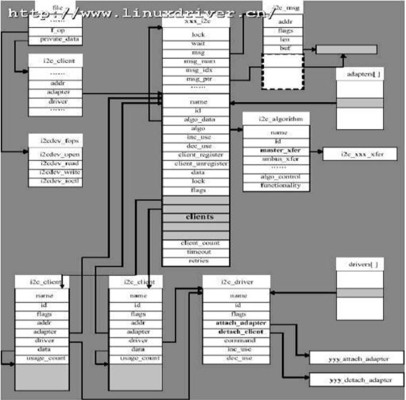
假設I2C匯流排介面卡xxx上有兩個使用相同驅動程式的yyyI2C裝置,在開啟I2C匯流排的裝置節點後相關資料結構之間的邏輯組織關係將如下圖所示:
圖5 I2C匯流排的裝置節點後相關資料結構之間的邏輯組織關係圖
從上面的分析可知,雖然I2C硬體體系結構簡單,但是I2C體系結構在linux中的實現卻相當複雜。當工程師拿到實際的電路板,面對複雜的linux I2C子系統,應該如何下手寫驅動呢?究竟要哪些是需要親自做的,哪些是核心已經提供的呢?理清這個問題非常有意義,可以使我們面對具體問題時迅速地抓住重點。
一方面,介面卡驅動可能是linux核心本身還不包含的;另一方面,掛接在介面卡上的就提裝置可能也是linux核心還不包含的。因此,工程師要實現的主要工作如下。
提供I2C介面卡的硬體驅動,探測、初始化I2C介面卡(如申請I2C的I/O地址和中斷號)、驅動CPU控制的I2C介面卡從硬體上產生各種訊號以及處理I2C中斷等。
提供I2C介面卡的algorithm,具體介面卡的xxx_xfer()函式填充i2c_algorithm的master_xfer指標,並把i2c_algorithm指標賦值給i2c_adapter的algo指標。
實現I2C裝置驅動中的i2c_driver介面,具體裝置yyy_probe()、yyy_remove()、yyy_suspend()、yyy_resume()函式指標和i2c_device_id裝置ID表賦值給i2c_driver的probe、remove
Linux 裝置驅動篇之-------I2c裝置驅動
雖然I2C硬體體系結構和協議都很容易理解,但是Linux I2C驅動體系結構卻有相當的複雜度,它主要由3部分組成,即I2C裝置驅動、I2C匯流
Linux 裝置驅動篇之I2c裝置驅動fulinux一、I2C驅動體系雖然I2C硬體體系結構和協議都很容易理解,但是Linux I2C驅動體系結構卻有相當的複雜度,它主要由3部分組成,即I2C裝置驅動、
pr_debug("bus: '%s': %s: bound device %s to driver %s\n", drv->bus->name, __func__, dev_name(dev), drv->name);
Zephyr OS 驅動篇之裝置初始化順序在前面的 Zephyr OS 驅動篇之裝置驅動模型 中已講解了 Zephyr OS 中的
Linux裝置驅動工程師之路——裝置模型(上)底層模型
K-Style
一、重要知識點
1.Sysfs檔案系統
Sysfs檔案系統是一種類似於proc檔案系統的特殊檔案系統,它存在於記憶體當中,當系統啟動時由核心掛載於記憶體當中。用於將
11.6 按鍵驅動程式例項
11.6.1 按鍵工作原理
高電平和低電平相接怎麼會變成低電平呢
就像你把電源正極的負極相連一樣會把電壓拉低。大電流會從高電平引腳流向低電平引腳,把高電平引腳拉低。
LED和蜂鳴器是最簡單的GPIO的應用,都不需要任何外部
linux驅動註冊過程分析--driver_register(一)
個人筆記,歡迎轉載,請註明出處,共同分享 共同進步
http://blog.csdn.net/richard_liujh/article/details/45825333
kernel版本3.10.1
建立裝置檔案的方法:
第一種是使用mknod手工建立:mknod filename type major minor
第二種是自動建立裝置節點:利用udev(mdev)來實現裝置檔案的自動建立,首先應保證支援udev(mdev),由busybox配置。
16.1 字元裝置驅動程式框架簡介
我們在學習 C 語言的時候,知道每個應用程式的入口函式,即第一個被執行的函式是 main函式,那麼,我們自己的驅動程式,哪個函式是入口函式呢?
在寫驅動程式的時候,如果函式的名字可以任意取,常常為 xxxx_init(),
很久沒寫日誌,主要最近工作比較繁忙,最近主要做乙太網開發的。
平臺: 高通 ,android 4.3 ,linux 3.4.0
這一部分,主要說一下,除錯過程中用到的一些命令。乙太網,是由usb轉ne
1 硬體特性
1.1 概述
I2C匯流排是由Philips公司開發的兩線式序列匯流排,這兩根線為時鐘線(SCL)和雙向資料線(SDA)。由於I2C匯流排僅需要兩根線,因此在電路板上佔用的空間更少,帶來的問題是頻寬較窄。I2C在標準模式下傳輸速率最高100Kb/s,在快速模式下最高可達400kb/s。屬於半
本次我們來說一下SDIO子系統的控制器的開發部分,這部分也是和硬體平臺相關的,在說這個之前,我們先來了解一下相關硬體的基礎知識和概念.
MMC
MMC全稱MultiMedia Card,由西門子公司和SanDisk公司1997年推出的多媒體記憶卡標準。MMC卡尺寸為32mm
在對zynq進行linux驅動開發時,除了需要針對zynq內ARM自帶的控制器適配驅動外,還需要對zynq PL部分的IP核進行驅動開發。對於ARM來說,zynq PL部分的IP核就是一段地址空間,這段地址空間包含了該IP的一系列暫存器,ARM操作該IP核的暫存器也就是
然後看這裡是怎樣註冊spi主機控制器驅動的:
int spi_register_master(struct spi_master *master)
{
。。。。。。。。。。。。。。。。
/*將spi新增到核心,這
來自:http://blog.csdn.net/woshixingaaa/article/details/6574220
這篇來分析spi子系統的建立過程。
嵌入式微處理器訪問SPI裝置有兩種方式:使用GPIO模擬SPI介面的工作時序或者使用SPI控制
1.概述:I²C 是Inter-Integrated Circuit的縮寫,發音為"eye-squaredcee" or "eye-two-cee" , 它是一種兩線介面。I²C 只是用兩條雙向的線,一條 Serial Data Line (SDA) ,另一條Serial
SPI驅動架構,以前用過,不過沒這個詳細,跟各位一起分享:
來自:http://blog.csdn.net/woshixingaaa/article/details/6574215
SPI協議是一種同步的序列資料連線標準,由摩托羅拉公司命名,可工作於全雙工模式。相
編寫I2C外設驅動步驟
註冊I2C裝置,一般在板級檔案中,定義i2c_board_info
註冊I2C驅動:i2c_register_driver,i2c_del_driver
利用i2c_client中的addr(裝置地址)和adapter(主機驅動)實現
spi_async在spi.h中定義的:
<span style="font-size:18px;">staticinlineint
spi_async(struct spi_device *spi, struct spi_mess >[系列目錄](https://www.cnblogs.com/tylerzhou/p/11204826.html)
Nunit裡提供了豐富的資料測試功能,雖然Xunit裡提供的比較少,但是也能滿足很多場景下使用了,如果資料場景非常複雜,Nunit和Xunit都是無法勝任的,有不少測試者選擇自己編寫一個 相關推薦
Linux 裝置驅動篇之-------I2c裝置驅動(待續)
Linux 裝置驅動篇之I2c裝置驅動
linux powerpc i2c驅動 之 i2c裝置…
Zephyr OS 驅動篇之裝置初始化順序
Linux裝置驅動工程師之路——裝置模型(上)底層模型
嵌入式Linux裝置驅動開發之:按鍵驅動程式例項
linux驅動篇之 driver_register 過程分析(一)
Android音訊驅動-ASOC之建立裝置節點
第16章 驅動開發之字元裝置驅動程式框架
初入android驅動開發之網路裝置乙太網(一)
Linux驅動子系統之I2C(一)
⑳tiny4412 Linux驅動開發之MMC子系統驅動程式
Zynq-Linux移植學習筆記之14-RapidIO驅動開發
Linux驅動修煉之道-SPI驅動框架原始碼分析(中-續)
Linux驅動修煉之道-SPI驅動框架原始碼分析(中)
android底層驅動學習之I2C概述及工作原理(一)
Linux驅動修煉之道-SPI驅動框架原始碼分析(上)
【Linux核心驅動】編寫I2C外設驅動讀取觸控式螢幕韌體版本
Linux驅動修煉之道-SPI驅動框架原始碼分析(下-續)
.netcore持續整合測試篇之Xunit資料驅動測試

