
linux核心驅動 TI OMAP類處理器的LED所涉及到裝置樹彙整
樣例擷取自linux4.1.13中,與裝置樹有關BeagleBone Black 的部分程式碼,
1、 定位GPIO控制器在處理的外圍地址:

GPIO0 記憶體對映:

GPIO1 記憶體對映:

GPIO2、GPIO3 記憶體對映:

2、CONTROL_MODULE控制模式的暫存器位置:

3、引腳複用地址: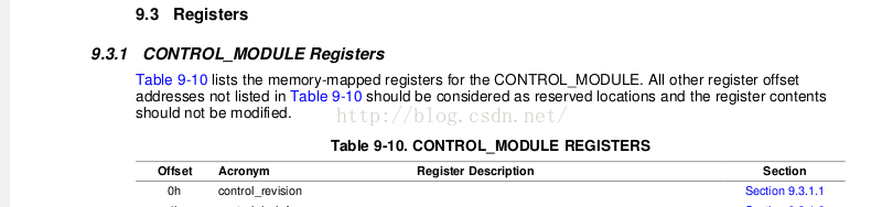

4、 Linux裝置樹對上述GPIO對映的實現如下:
/ {
compatible = "ti,am33xx";
interrupt-parent = <&intc>;
ocp {
compatible = "simple-bus";
#address-cells = <1>;
#size-cells = <1>;
ranges;
ti,hwmods = "l3_main";
gpio0: 5、控制模式器和引腳複用記憶體對映
ocp {
        compatible = "simple-bus";
        #address-cells = <1>;
        #size-cells = <1>;
        ranges;
        ti,hwmods = "l3_main";

        l4_wkup: [email protected] {
            compatible = "ti,am3-l4-wkup", "simple-bus";
            #address-cells = <1>;
            #size-cells = <1>;
            ranges = <0 0x44c00000 0x280000>;

                scm: [email protected] {
                compatible = "ti,am3-scm", "simple-bus";
                reg = <0x210000 0x2000>;
                #address-cells = <1>;
                #size-cells = <1>;
                ranges = <0 0x210000 0x2000>;

/*

*計算下 控制模式的地址 = 0x44c00000+0x210000=0x44E1000

*引腳複用地址=0x44E1000+0x800 = 0x44E10800

*/

                am33xx_pinmux: [email protected] {
                    compatible = "pinctrl-single";
                    reg = <0x800 0x238>;
                    #address-cells = <1>;
                    #size-cells = <0>;
                    pinctrl-single,register-width = <32>;
                    pinctrl-single,function-mask = <0x7f>;
                };

           };

  };
6、開啟處理器的內部引腳複用、上下拉等屬性有關的CONTROL_MODULE:
TI的處理器有專門的控制器模式,用於設定IO屬性。處理器的部分引腳有複用功能,必須記得設定引腳複用單元,此處開啟的是beaglebone black上的4個usr led,其詳細的引腳位置不貼出了,請查閱相關手冊。
&am33xx_pinmux {
    pinctrl-names = "default";
    pinctrl-0 = <&clkout2_pin>;

    user_leds_s0: user_leds_s0 {
        pinctrl-single,pins = <
            0x54 (PIN_OUTPUT_PULLDOWN | MUX_MODE7)    /* gpmc_a5.gpio1_21 */
            0x58 (PIN_OUTPUT_PULLUP | MUX_MODE7)    /* gpmc_a6.gpio1_22 */
            0x5c (PIN_OUTPUT_PULLDOWN | MUX_MODE7)    /* gpmc_a7.gpio1_23 */
            0x60 (PIN_OUTPUT_PULLUP | MUX_MODE7)    /* gpmc_a8.gpio1_24 */
     >;
   }

}
7、linux核心與驅動LED有關的裝置樹實現:
/{

leds {
        pinctrl-names = "default";
        pinctrl-0 = <&user_leds_s0>;

        compatible = "gpio-leds";

        [email protected] {
            label = "beaglebone:green:heartbeat";
            gpios = <&gpio1 21 GPIO_ACTIVE_HIGH>;
            linux,default-trigger = "heartbeat";
            default-state = "off";
        };

        [email protected] {
            label = "beaglebone:green:mmc0";
            gpios = <&gpio1 22 GPIO_ACTIVE_HIGH>;
            linux,default-trigger = "mmc0";
            default-state = "off";
        };

        [email protected] {
            label = "beaglebone:green:usr2";
            gpios = <&gpio1 23 GPIO_ACTIVE_HIGH>;
            linux,default-trigger = "cpu0";
            default-state = "off";
        };

        [email protected] {
            label = "beaglebone:green:usr3";
            gpios = <&gpio1 24 GPIO_ACTIVE_HIGH>;
            linux,default-trigger = "mmc1";
            default-state = "off";
        };

}
8、 TI處理器有關的linux核心對有關的gpio、pinctrl-single、gpio-leds的裝置樹屬性定義的描述:
8.1 ti, omap2-gpio 屬性描述,摘自核心的目錄下的/Documentation/devicetree/bindings/gpio/gpio-omap.txt
OMAP GPIO controller bindings

Required properties:
- compatible:
  - "ti,omap2-gpio" for OMAP2 controllers
  - "ti,omap3-gpio" for OMAP3 controllers
  - "ti,omap4-gpio" for OMAP4 controllers
- gpio-controller : Marks the device node as a GPIO controller.
- #gpio-cells : Should be two.
  - first cell is the pin number
  - second cell is used to specify optional parameters (unused)
- interrupt-controller: Mark the device node as an interrupt controller.
- #interrupt-cells : Should be 2.
  The first cell is the GPIO number.
  The second cell is used to specify flags:
    bits[3:0] trigger type and level flags:
      1 = low-to-high edge triggered.
      2 = high-to-low edge triggered.
      4 = active high level-sensitive.
      8 = active low level-sensitive.

OMAP specific properties:
- ti,hwmods:        Name of the hwmod associated to the GPIO:
            "gpio<X>", <X> being the 1-based instance number
            from the HW spec.
- ti,gpio-always-on:     Indicates if a GPIO bank is always powered and
            so will never lose its logic state.


Example:

gpio4: gpio4 {
    compatible = "ti,omap4-gpio";
    ti,hwmods = "gpio4";
    gpio-controller;
    #gpio-cells = <2>;
    interrupt-controller;
    #interrupt-cells = <2>;
};
8.2 pinctrl-single,摘自核心的目錄下的/Documentation/devicetree/bindings/pinctrl/pinctrl-single.txt
One-register-per-pin type device tree based pinctrl driver

Required properties:
- compatible : "pinctrl-single" or "pinconf-single".
  "pinctrl-single" means that pinconf isn't supported.
  "pinconf-single" means that generic pinconf is supported.

- reg : offset and length of the register set for the mux registers

- pinctrl-single,register-width : pinmux register access width in bits

- pinctrl-single,function-mask : mask of allowed pinmux function bits
  in the pinmux register

Optional properties:
- pinctrl-single,function-off : function off mode for disabled state if
  available and same for all registers; if not specified, disabling of
  pin functions is ignored

- pinctrl-single,bit-per-mux : boolean to indicate that one register controls
  more than one pin, for which "pinctrl-single,function-mask" property specifies
 position mask of pin.

- pinctrl-single,drive-strength : array of value that are used to configure
  drive strength in the pinmux register. They're value of drive strength
  current and drive strength mask.

		/* drive strength current, mask */
		pinctrl-single,power-source = <0x30 0xf0>;

- pinctrl-single,bias-pullup : array of value that are used to configure the
  input bias pullup in the pinmux register.

		/* input, enabled pullup bits, disabled pullup bits, mask */
		pinctrl-single,bias-pullup = <0 1 0 1>;

- pinctrl-single,bias-pulldown : array of value that are used to configure the
  input bias pulldown in the pinmux register.

		/* input, enabled pulldown bits, disabled pulldown bits, mask */
		pinctrl-single,bias-pulldown = <2 2 0 2>;

  * Two bits to control input bias pullup and pulldown: User should use
    pinctrl-single,bias-pullup & pinctrl-single,bias-pulldown. One bit means
    pullup, and the other one bit means pulldown.
  * Three bits to control input bias enable, pullup and pulldown. User should
    use pinctrl-single,bias-pullup & pinctrl-single,bias-pulldown. Input bias
    enable bit should be included in pullup or pulldown bits.
  * Although driver could set PIN_CONFIG_BIAS_DISABLE, there's no property as
    pinctrl-single,bias-disable. Because pinctrl single driver could implement
    it by calling pulldown, pullup disabled.

- pinctrl-single,input-schmitt : array of value that are used to configure
  input schmitt in the pinmux register. In some silicons, there're two input
  schmitt value (rising-edge & falling-edge) in the pinmux register.

		/* input schmitt value, mask */
		pinctrl-single,input-schmitt = <0x30 0x70>;

- pinctrl-single,input-schmitt-enable : array of value that are used to
  configure input schmitt enable or disable in the pinmux register.

		/* input, enable bits, disable bits, mask */
		pinctrl-single,input-schmitt-enable = <0x30 0x40 0 0x70>;

- pinctrl-single,low-power-mode : array of value that are used to configure
  low power mode of this pin. For some silicons, the low power mode will
  control the output of the pin when the pad including the pin enter low
  power mode.
		/* low power mode value, mask */
		pinctrl-single,low-power-mode = <0x288 0x388>;

- pinctrl-single,gpio-range : list of value that are used to configure a GPIO
  range. They're value of subnode phandle, pin base in pinctrl device, pin
  number in this range, GPIO function value of this GPIO range.
  The number of parameters is depend on #pinctrl-single,gpio-range-cells
  property.

		/* pin base, nr pins & gpio function */
		pinctrl-single,gpio-range = <&range 0 3 0 &range 3 9 1>;

- interrupt-controller : standard interrupt controller binding if using
  interrupts for wake-up events for example. In this case pinctrl-single
  is set up as a chained interrupt controller and the wake-up interrupts
  can be requested by the drivers using request_irq().

- #interrupt-cells : standard interrupt binding if using interrupts

This driver assumes that there is only one register for each pin (unless the
pinctrl-single,bit-per-mux is set), and uses the common pinctrl bindings as
specified in the pinctrl-bindings.txt document in this directory.

The pin configuration nodes for pinctrl-single are specified as pinctrl
register offset and value pairs using pinctrl-single,pins. Only the bits
specified in pinctrl-single,function-mask are updated. For example, setting
a pin for a device could be done with:

	pinctrl-single,pins = <0xdc 0x118>;

Where 0xdc is the offset from the pinctrl register base address for the
device pinctrl register, and 0x118 contains the desired value of the
pinctrl register. See the device example and static board pins example
below for more information.

In case when one register changes more than one pin's mux the
pinctrl-single,bits need to be used which takes three parameters:

	pinctrl-single,bits = <0xdc 0x18 0xff>;

Where 0xdc is the offset from the pinctrl register base address for the
device pinctrl register, 0x18 is the desired value, and 0xff is the sub mask to
be used when applying this change to the register.


Optional sub-node: In case some pins could be configured as GPIO in the pinmux
register, those pins could be defined as a GPIO range. This sub-node is required
by pinctrl-single,gpio-range property.

Required properties in sub-node:
- #pinctrl-single,gpio-range-cells : the number of parameters after phandle in
  pinctrl-single,gpio-range property.

	range: gpio-range {
		#pinctrl-single,gpio-range-cells = <3>;
	};


Example:

/* SoC common file */

/* first controller instance for pins in core domain */
pmx_core: [email protected] {
	compatible = "pinctrl-single";
	reg = <0x4a100040 0x0196>;
	#address-cells = <1>;
	#size-cells = <0>;
	#interrupt-cells = <1>;
	interrupt-controller;
	pinctrl-single,register-width = <16>;
	pinctrl-single,function-mask = <0xffff>;
};

/* second controller instance for pins in wkup domain */
pmx_wkup: [email protected] {
	compatible = "pinctrl-single";
	reg = <0x4a31e040 0x0038>;
	#address-cells = <1>;
	#size-cells = <0>;
	#interrupt-cells = <1>;
	interrupt-controller;
	pinctrl-single,register-width = <16>;
	pinctrl-single,function-mask = <0xffff>;
};

control_devconf0: [email protected] {
	compatible = "pinctrl-single";
	reg = <0x48002274 4>;	/* Single register */
	#address-cells = <1>;
	#size-cells = <0>;
	pinctrl-single,bit-per-mux;
	pinctrl-single,register-width = <32>;
	pinctrl-single,function-mask = <0x5F>;
};

/* third controller instance for pins in gpio domain */
pmx_gpio: [email protected] {
	compatible = "pinconf-single";
	reg = <0xd401e000 0x0330>;
	#address-cells = <1>;
	#size-cells = <1>;
	ranges;

	pinctrl-single,register-width = <32>;
	pinctrl-single,function-mask = <7>;

	/* sparse GPIO range could be supported */
	pinctrl-single,gpio-range = <&range 0 3 0 &range 3 9 1
				&range 12 1 0 &range 13 29 1
				&range 43 1 0 &range 44 49 1
				&range 94 1 1 &range 96 2 1>;

	range: gpio-range {
		#pinctrl-single,gpio-range-cells = <3>;
	};
};


/* board specific .dts file */

&pmx_core {

	/*
	 * map all board specific static pins enabled by the pinctrl driver
	 * itself during the boot (or just set them up in the bootloader)
	 */
	pinctrl-names = "default";
	pinctrl-0 = <&board_pins>;

	board_pins: pinmux_board_pins {
		pinctrl-single,pins = <
			0x6c 0xf
			0x6e 0xf
			0x70 0xf
			0x72 0xf
		>;
	};

	uart0_pins: pinmux_uart0_pins {
		pinctrl-single,pins = <
			0x208 0		/* UART0_RXD (IOCFG138) */
			0x20c 0		/* UART0_TXD (IOCFG139) */
		>;
		pinctrl-single,bias-pulldown = <0 2 2>;
		pinctrl-single,bias-pullup = <0 1 1>;
	};

	/* map uart2 pins */
	uart2_pins: pinmux_uart2_pins {
		pinctrl-single,pins = <
			0xd8 0x118
			0xda 0
			0xdc 0x118
			0xde 0
		>;
	};
};

&control_devconf0 {
	mcbsp1_pins: pinmux_mcbsp1_pins {
		pinctrl-single,bits = <
			0x00 0x18 0x18 /* FSR/CLKR signal from FSX/CLKX pin */
		>;
	};

	mcbsp2_clks_pins: pinmux_mcbsp2_clks_pins {
		pinctrl-single,bits = <
			0x00 0x40 0x40 /* McBSP2 CLKS from McBSP_CLKS pin */
		>;
	};

};

&uart1 {
       pinctrl-names = "default";
       pinctrl-0 = <&uart0_pins>;
};

&uart2 {
       pinctrl-names = "default";
       pinctrl-0 = <&uart2_pins>;
};
8.3 gpio-leds,摘自核心的目錄下的/Documentation/devicetree/bindings/leds/txtleds-gpio.txt
LEDs connected to GPIO lines

Required properties:
- compatible : should be "gpio-leds".

Each LED is represented as a sub-node of the gpio-leds device.  Each
node's name represents the name of the corresponding LED.

LED sub-node properties:
- gpios :  Should specify the LED's GPIO, see "gpios property" in
  Documentation/devicetree/bindings/gpio/gpio.txt.  Active low LEDs should be
  indicated using flags in the GPIO specifier.
- label :  (optional)
  see Documentation/devicetree/bindings/leds/common.txt
- linux,default-trigger :  (optional)
  see Documentation/devicetree/bindings/leds/common.txt
- default-state:  (optional) The initial state of the LED.  Valid
  values are "on", "off", and "keep".  If the LED is already on or off
  and the default-state property is set the to same value, then no
  glitch should be produced where the LED momentarily turns off (or
  on).  The "keep" setting will keep the LED at whatever its current
  state is, without producing a glitch.  The default is off if this
  property is not present.
- retain-state-suspended: (optional) The suspend state can be retained.Such
  as charge-led gpio.

Examples:

#include <dt-bindings/gpio/gpio.h>

leds {
    compatible = "gpio-leds";
    hdd {
        label = "IDE Activity";
        gpios = <&mcu_pio 0 GPIO_ACTIVE_LOW>;
        linux,default-trigger = "ide-disk";
    };

    fault {
        gpios = <&mcu_pio 1 GPIO_ACTIVE_HIGH>;
        /* Keep LED on if BIOS detected hardware fault */
        default-state = "keep";
    };
};

run-control {
    compatible = "gpio-leds";
    red {
        gpios = <&mpc8572 6 GPIO_ACTIVE_HIGH>;
        default-state = "off";
    };
    green {
        gpios = <&mpc8572 7 GPIO_ACTIVE_HIGH>;
        default-state = "on";
    };
};

leds {
    compatible = "gpio-leds";

    charger-led {
        gpios = <&gpio1 2 GPIO_ACTIVE_HIGH>;
        linux,default-trigger = "max8903-charger-charging";
        retain-state-suspended;
    };
};
Documentation/devicetree/bindings/leds/common.txt
Common leds properties.

LED and flash LED devices provide the same basic functionality as current
regulators, but extended with LED and flash LED specific features like
blinking patterns, flash timeout, flash faults and external flash strobe mode.

Many LED devices expose more than one current output that can be connected
to one or more discrete LED component. Since the arrangement of connections
can influence the way of the LED device initialization, the LED components
have to be tightly coupled with the LED device binding. They are represented
by child nodes of the parent LED device binding.

Optional properties for child nodes:
- led-sources : List of device current outputs the LED is connected to. The
        outputs are identified by the numbers that must be defined
        in the LED device binding documentation.
- label : The label for this LED. If omitted, the label is taken from the node
      name (excluding the unit address). It has to uniquely identify
      a device, i.e. no other LED class device can be assigned the same
      label.

- linux,default-trigger :  This parameter, if present, is a
    string defining the trigger assigned to the LED.  Current triggers are:
     "backlight" - LED will act as a back-light, controlled by the framebuffer
           system
     "default-on" - LED will turn on (but for leds-gpio see "default-state"
            property in Documentation/devicetree/bindings/gpio/led.txt)
     "heartbeat" - LED "double" flashes at a load average based rate
     "ide-disk" - LED indicates disk activity
     "timer" - LED flashes at a fixed, configurable rate

- max-microamp : maximum intensity in microamperes of the LED
         (torch LED for flash devices)
- flash-max-microamp : maximum intensity in microamperes of the
                       flash LED; it is mandatory if the LED should
               support the flash mode
- flash-timeout-us : timeout in microseconds after which the flash
                     LED is turned off


Examples:

system-status {
    label = "Status";
    linux,default-trigger = "heartbeat";
    ...
};

camera-flash {
    label = "Flash";
    led-sources = <0>, <1>;
    max-microamp = <50000>;
    flash-max-microamp = <320000>;
    flash-timeout-us = <500000>;
};
9.總結:
開發一個led的驅動,實質涉及就兩大塊:其一就是硬體底層有關的實現,其二就是呼叫硬體底層來實現使用者功能(低階使用者功能)。
本例在硬體底層中,涉及的主要是gpio控制、控制模式的引腳複用,而要使她們能正常工作,又需要載入相應的驅動模組,而裝置樹的“compatible”為其找尋相應的驅動提供了路徑,
led使用者層的功能的驅動就要勞駕“gpio-leds” --compatible 屬性來實現。
參考:
1、AM335x ARM ® CortexTM-A8 Microprocessors (MPUs) Technical Reference Manual
2、 linux4.1.13
備註:
1。 20160206, wiwa 完成初稿
相關推薦
linux核心驅動 TI OMAP類處理器的LED所涉及到裝置樹彙整
樣例擷取自linux4.1.13中,與裝置樹有關BeagleBone Black 的部分程式碼,1、 定位GPIO控制器在處理的外圍地址: GPIO0 記憶體對映: GPIO1 記憶體對映: GPIO2、GPIO3 記憶體對映: 2、CONTROL_MODULE控
Android/Linux核心驅動相關經典書籍大合集(Linux驅動工程師必備)
博主從事嵌入式Linux核心驅動開發工作,在工作學習中收集了一些Linux核心驅動開發相關的經典書籍,最近將這些經典書籍陸續以資源的形式傳到了CSDN上,希望能給同行以幫助,但因為博主下載積分級別關係,還有些經典書籍(像《深入Linux核心架構中文版》(現已經傳上見第
linux核心驅動重要的資料結構
檔案操作 迄今為止, 我們已經保留了一些裝置編號給我們使用, 但是我們還沒有連線任何我們裝置操作到這些編號上. file_operation 結構是一個字元驅動如何建立這個連線. 這個結構, 定義在 , 是一個函式指標的集合. 每個開啟檔案(內部用一個 file
Linux 核心驅動中對檔案的讀寫
有時候需要在Linux kernel–大多是在需要除錯的驅動程式–中讀寫檔案資料。在kernel中操作檔案沒有標準庫可用,需要利用kernel的一些函式,這些函式主 要有: filp_open() filp_close(), vfs_read() vfs_write
Eclipse 搭建 Linux 核心驅動程式開發環境
1、開發工具 eclipse 、arm-linux-gcc交叉工具鏈、對應開發板的Linux 核心原始碼。2、安裝開發工具,並將核心原始碼包解壓到指定路徑中,並編譯。 eg:/usr/local/arm/linux_E9_3.0.35_for_Linux3、利用eclipse
Linux核心驅動之GPIO子系統(一)GPIO的使用
四 使用者態使用gpio監聽中斷 首先需要將該gpio配置為中斷 echo "rising" > /sys/class/gpio/gpio12/edge 以下是虛擬碼 int gpio_id; struct pollfd fds[1]; gpio_fd = open("/s
Linux核心驅動學習(二)----根檔案系統的構成 (root filesystem)
1、建立根檔案系統目錄和檔案 1.1建立目錄 1.2建立裝置檔案(命令mknod);必須建立裝置檔案---consle\null 1.3建立配置檔案---複製已有的/etc目錄下的檔案
Linux核心驅動GPIO的使用
一 概述 Linux核心中gpio是最簡單,最常用的資源(和 interrupt ,dma,timer一樣)驅動程式,應用程式都能夠通過相應的介面使用gpio,gpio使用0~MAX_INT之間的整數標識,不能使用負數,gpio與硬體體系密切相關的,不過linux有
ARM Linux核心驅動異常定位除錯--反彙編arm-linux-objdump
最近在搞Atmel 的SAM9x25平臺,Linux系統,用於工業裝置。這也是我首次參與工業裝置的研發。在除錯Atmel SAM9x25的Linux串列埠裝置的時候,發現無論是讀還是寫,都會產生異常。相關的異常資訊如下: ===========================================
Linux核心驅動基礎-裝置樹相關匯流排使用
mmc匯流排使用例項 broken-cd 表示沒有熱插拔探測引腳,使用輪詢檢測 cd-gpios 使用gpio管腳作為熱插拔探測引腳 non-removable 表示不能進行熱插拔,裝置一直連線(比如eMMC) 上面三個選項用於指定熱插拔探測選項,如果三個選項都沒有指
Arm+Linux核心驅動學習筆記
韋東山老師幫我們把框架搭建起來了,我們先來看一下: 框架: app: open,read,write "1.txt" --------------------------------------------- 檔案的讀寫 檔案系統: vfat, ext2,
linux核心驅動同步、非同步、併發
本部落格內容會不定期更新 --------------------------------------------------------------------Miscellaneous------------------------------------------
【Linux核心驅動】編寫I2C外設驅動讀取觸控式螢幕韌體版本
編寫I2C外設驅動步驟 註冊I2C裝置,一般在板級檔案中,定義i2c_board_info 註冊I2C驅動:i2c_register_driver,i2c_del_driver 利用i2c_client中的addr(裝置地址)和adapter(主機驅動)實現
Linux核心驅動學習(四)----記憶體管理子系統
kmalloc()和vmalloc()介紹 kmalloc() 用於申請較小的、連續的實體記憶體 1. 以位元組為單位進行分配,在<linux/slab.h>中 2. void *kmalloc(size_t size, int flags) 分配的記憶體實體地址上連續,虛擬地址上自然
Linux核心驅動模組編譯
核心模組的構建有兩種主要方式:放在核心原始碼樹中或者放在核心程式碼外。 一、放在核心原始碼樹中 在核心的drivers/資料夾下建立好驅動模組資料夾,並完成驅動檔案之後,需要編輯和修改相應的Kconfig和Makefile檔案,使得該模組可以配置到核心中並進行編譯。 1.
基於ubuntu14.04 Linux核心驅動的編寫
兩種方式:(1)靜態申請 函式 int register_chrdev_region(dev_t from,unsigned count, const char *name); / * register_chrdev_region() - register arange of devi
在Ubuntu上為Android系統編寫Linux核心驅動程式
在智慧手機時代,每個品牌的手機都有自己的個性特點。正是依靠這種與眾不同的個性來吸引使用者,營造品牌凝聚力和使用者忠城度,典型的代表非iphone莫屬了。據統計,截止2011年5月,AppStore的應用軟體數量達381062個,位居第一,而Android Ma
Linux核心驅動之延時
使用場景: 延後一定的時間執行特定的程式碼 根據延時時間的長短分為“長延時”和“短延時” 長延時: 1.忙等待 while (time_before(jiffies, j1)) cpu_relax();這裡j1是jiffies延時超時的值 2.讓出處理器 wh
linux 核心模組程式設計之LED驅動程式(六)
我使用的是tiny6410的核心板,板子如下,淘寶可以買到 為了不與板子上的任何驅動發生IO衝突,我使用CON1那一排沒用到的IO口,引腳如下 LED1 LED2 LED3 LED4
Linux核心模組驅動之---led驅動
/**************************************************************************/ /***************************led.c********************************************