
鏈路聚合配置命令
1.1 概述
1.1.1 鏈路聚合簡介
在路由器上使用多鏈路進行互連時,可以把多條物理鏈路進行捆綁,對外呈現一條邏輯鏈路,並遮蔽實際的物理鏈路。這種方式稱之為鏈路聚合(Aggregate,簡稱AG),且把實際的物理鏈路稱之為AG的成員鏈路。銳捷裝置所提供的AG功能符合IEEE802.3ad標準,它可以用於擴充套件鏈路頻寬,提供更高的連線可靠性。
AG功能支援流量平衡,可以把流量均勻地分配給各成員鏈路。AG功能還實現了鏈路備份,當AG中的一條成員鏈路斷開時,系統會將該成員鏈路的流量自動地分配到AG中的其它有效成員鏈路上去。AG中一條成員鏈路收到的廣播或者多播報文,將不會被轉發到其它成員鏈路上。
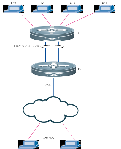
圖 1‑1 典型拓撲場景
路由器上每個AG口最多包含的成員口數量都為8個。
1.1.2 流量均衡簡介
AG可以根據報文的源IP地址,目的IP地址,源IP地址+目的IP及源IP和目的埠號等特徵值把流量平均地分配到AG的成員鏈路中。可以在介面模式下用route-aggregateportload-balance設定流量分配方式。
“源IP流量平衡”是根據報文的源IP把報文分配到AG的各個成員鏈路中。不同源IP的報文根據源IP在各成員鏈路間平衡分配,相同源IP的報文,固定從同一個成員鏈路轉發。該方式為三層AG預設的流量平衡方式。
“目的IP流量平衡”是根據報文的目的IP把報文分配到AG的各個成員鏈路中。相同目的
“源IP地址+目的IP流量平衡”是根據報文的源IP地址+目的IP把報文分配到AP的各個成員鏈路中。具有不同的源IP地址+目的IP的報文根據源IP地址+目的IP在各成員鏈路間平衡分配,而具有相同的源IP地址+目的IP的報文則固定分配給同一個成員鏈路。
“源IP和目的埠號流量平衡”是根據源IP和目的埠號進行流量分配。不同源IP和目的埠號的報文根據源IP和目的埠號在各成員鏈路間平衡分配,相同源IP和目的埠號的報文則固定通過相同的成員鏈路轉發。
當前在路由器上的流量均衡主要由:源IP、目的IP、源埠號、目的埠號為元素的組合進行流量平衡。在路由器
我們應根據不同的網路環境設定合適的流量分配方式,以便能把流量較均勻地分配到各個鏈路上,充分利用網路的頻寬。
相關的協議規範或參見的標準:
802.1AX-2014 - IEEE Standard for Local and metropolitan areanetworks -- Link Aggregation
RFC7130, Bidirectional Forwarding Detection (BFD) on LinkAggregation Group (LAG) Interfaces
配置步驟
配置舉例
組網需求
為了提高頻寬和鏈路可靠性,RouterA與RouterB之間通過不同的運營商鏈路進行互連
配置要點
l RouterA和RouterB上分別建立AG口,分別將gi 0/0和gi 0/1加入AG口;
l RouterA和RouterB上AG口配置IP地址及BFD會話。
配置步驟
1) 在RouterA上建立AG口1,並將gi 0/0和gi 0/1加入AG口:
RouterA#configure terminal
RouterA(config)#interfaceroute-aggregateport 1
RouterA(config-if-Route-aggregateport1)#exit
RouterA(config)#
RouterA(config)#interfacegigabitEthernet 0/0
RouterA(config-if-GigabitEthernet0/0)#route-port-group 1
RouterA(config-if-GigabitEthernet0/0)#exit
RouterA(config)#
RouterA(config)#interfacegigabitEthernet 0/1
RouterA(config-if-GigabitEthernet0/1)#route-port-group 1
RouterA(config-if-GigabitEthernet0/1)#exit
2) RouterA上的AG口配置IP地址及BFD會話。
RouterA(config)#
RouterA(config)#interfaceroute-aggregateport 1
RouterA(config-if-Route-aggregateport1)#ip address 124.115.8.1 255.255.255.0
RouterA(config-if-Route-aggregateport1)#bfd interval 50 min_rx 50 multiplier 3
RouterA(config-if-Route-aggregateport1)#member interface GigabitEthernet 0/0 bind bfd peer-ip 124.115.8.2
RouterA(config-if-Route-aggregateport1)#member interface GigabitEthernet 0/1 bind bfd peer-ip 124.115.8.2
3) 在RouterB上建立AG口1,並將gi 0/0和gi 0/1加入AG口:
RouterB#configure terminal
RouterB(config)#interfaceroute-aggregateport 1
RouterB(config-if-Route-aggregateport1)#exit
RouterB(config)#
RouterB(config)#interfacegigabitEthernet 0/0
RouterB(config-if-GigabitEthernet0/0)#route-port-group 1
RouterB(config-if-GigabitEthernet0/0)#exit
RouterB(config)#
RouterB(config)#interfacegigabitEthernet 0/1
RouterB(config-if-GigabitEthernet0/1)#route-port-group 1
RouterB(config-if-GigabitEthernet0/1)#exit
4) RouterB上的AG口配置IP地址及BFD會話。
RouterB(config)#
RouterB(config)#interfaceroute-aggregateport 1
RouterB(config-if-Route-aggregateport1)#ip address 124.115.8.2 255.255.255.0
RouterB(config-if-Route-aggregateport1)#bfd interval 50 min_rx 50 multiplier 3
RouterB(config-if-Route-aggregateport1)#member interface GigabitEthernet 0/0 bind bfd peer-ip 124.115.8.1
RouterB(config-if-Route-aggregateport1)#member interface GigabitEthernet 0/1 bind bfd peer-ip 124.115.8.1
顯示驗證
1)檢視RouterA上的AG口的介面統計:
RouterA#show interfaceroute-aggregateport 1
Index(dec):35 (hex):23
Route-aggregateport 1 is UP , line protocol is UP
Hardware is Route-aggregateport, address is001a.a93e.dd31 (bia 001a.a93e.dd31)
Interface address is: 124.115.8.1/24
後面省略。。。。