並行資料流轉化為一種特殊序列資料流模組的設計
設計兩個可綜合的電路模組:第一個模組(M1)接受四位並行資料,並將其轉化為簡化I2C傳輸格式。sclk為輸入主鍾,data[3:0]為輸入的四位資料,ack為請求傳送資料訊號(請求後才有資料傳送到data[3:0]),資料流用scl和sda兩條線傳輸。第二個模組(M2)接收以簡化I2C協議通過scl和sda傳輸來的資料,並轉化為相應16條訊號線上的高電平,若資料為1,則第一條線路為高電平,資料為n,則第N條線路為高電平。模組如下圖所示。
本文引用自https://blog.csdn.net/llxxyy507/article/details/81046981

簡化的I2C通訊協議如下:scl為時鐘訊號,當scl為高電平的時候,sda從高電平變為低電平,表示序列資料流開始傳輸;當scl為高電平,sda從低電平變為高電平的時候,表示序列資料流結束。sda訊號只能在scl為低電平的時候變化,在scl為高電平期間應該維持穩定。
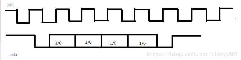
上圖中,sda訊號在scl為高時從高變低,為資料流的開始。在scl為低電平時傳輸第一位資料(MSB),並在整個scl為高的期間都維持訊號的穩定,接著傳遞剩下的資料。sda訊號在scl為高時從低變高,表示資料流的結束。
模組M1的verilog程式碼(ptosda.v)如下:
module ptosda(sclk,rst,data,ack,scl,sda);
input sclk,rst,data;
wire [3:0]data;

output scl,sda,ack;
reg scl,ack,link_sda,sdabuf;
reg [3:0]databuf;
reg [7:0]state;

out16hi m2(.scl(scl), .sda(sda), .outhigh() );    //呼叫M2模組

assign  sda = link_sda ? sdabuf : 1'b0;        //link_sda控制sdabuf輸出到序列總線上

parameter  ready  =  8'b0000_0000,
           start  =  8'b0000_0001,
           bit1   =  8'b0000_0010,
           bit2   =  8'b0000_0100,
           bit3   =  8'b0000_1000,
           bit4   =  8'b0001_0000,
           bit5   =  8'b0010_0000,
           stop   =  8'b0100_0000,
           IDLE   =  8'b1000_0000;

always @(posedge sclk or negedge rst)         //主鍾sclk產生序列輸出時鐘clk
       begin
              if (!rst)
                scl <= 1;
              else
                scl <= ~scl;
       end

always @(posedge ack)
       databuf <= data;

always @(negedge sclk or negedge rst)
       if (!rst)
           begin
                 link_sda <= 0;
                 state <= ready;
                 sdabuf <= 1;
                 ack <= 0;
           end
        else
           begin
              case(state)
              ready : if(ack)
                        begin
                           link_sda <= 1;
                           state <= start;
                        end
                      else
                        begin
                           link_sda <= 0;
                           state <= ready;
                           ack <= 1;
                        end

               start : if(scl && ack)
                         begin
                            sdabuf <= 0;
                            state <= bit1;
                         end
                       else
                         state <= start;

                bit1  : if(!scl)
                          begin
                             sdabuf <= databuf[3];
                             state <= bit2;
                             ack <= 0;
                          end
                         else
                          state <= bit1;

                bit2  : if(!scl)
                          begin
                             sdabuf <= databuf[2];
                             state <= bit3;
                          end
                         else
                          state <= bit2;

                bit3  : if(!scl)
                          begin
                             sdabuf <= databuf[1];
                             state <= bit4;
                          end
                         else
                          state <= bit3;

                bit4  : if(!scl)
                          begin
                             sdabuf <= databuf[0];
                             state <= bit5;
                          end
                         else
                          state <= bit4;

                bit5  : if(!scl)
                          begin
                             sdabuf <= 0;
                             state <= stop;
                          end
                         else
                          state <= bit5;

                stop  : if(scl)
                          begin
                             sdabuf <= 1;
                             state <= IDLE;
                          end
                         else
                          state <= stop;

                IDLE  :  begin
                             link_sda <= 0;
                             state <= ready;
                          end

               default  : begin
                             link_sda <= 0;
                             sdabuf <= 1;
                            state <= ready;
                          end
             endcase
          end
endmodule
模組M2(out16hi.v)verilog程式碼如下:
module out16hi(scl,sda,outhigh);
input scl,sda;
output [15:0]outhigh;

reg [4:0]mstate;
reg [3:0]pdata,pdatabuf;
reg [15:0]outhigh;
reg StartFlag,EndFlag;              //序列資料開始和結束標誌

always @(negedge sda)
     begin
       if (scl)
           StartFlag <= 1;
       else if (EndFlag)
           StartFlag <= 0;
     end

always @(posedge sda)
       if (scl)
          begin
            EndFlag <= 1;
				pdatabuf <= pdata;
          end
       else
            EndFlag <= 0;

parameter sbit0 = 5'b0_0001,
          sbit1 = 5'b0_0010,
          sbit2 = 5'b0_0100,
          sbit3 = 5'b0_1000,
          sbit4 = 5'b1_0000;

always @(pdatabuf)                              //接受到的資料轉化為相應的輸出位的高電平
       begin
         case(pdatabuf)
             4'b0001: outhigh = 16'b0000_0000_0000_0001;
             4'b0010: outhigh = 16'b0000_0000_0000_0010;
             4'b0011: outhigh = 16'b0000_0000_0000_0100;
             4'b0100: outhigh = 16'b0000_0000_0000_1000;
             4'b0101: outhigh = 16'b0000_0000_0001_0000;
             4'b0110: outhigh = 16'b0000_0000_0010_0000;
             4'b0111: outhigh = 16'b0000_0000_0100_0000;
             4'b1000: outhigh = 16'b0000_0000_1000_0000;
             4'b1001: outhigh = 16'b0000_0001_0000_0000;
             4'b1010: outhigh = 16'b0000_0010_0000_0000;
             4'b1011: outhigh = 16'b0000_0100_0000_0000;
             4'b1100: outhigh = 16'b0000_1000_0000_0000;
             4'b1101: outhigh = 16'b0001_0000_0000_0000;
             4'b1110: outhigh = 16'b0010_0000_0000_0000;
             4'b1111: outhigh = 16'b0100_0000_0000_0000;
             4'b0000: outhigh = 16'b1000_0000_0000_0000;
          endcase
         end

always @(posedge scl)
       if (StartFlag)
          case(mstate)
              sbit0 : begin
                        mstate <= sbit1;
                        pdata[3] <= sda;
                      end

              sbit1 : begin
                        mstate <= sbit2;
                        pdata[2] <= sda;
                      end

              sbit2 : begin
                        mstate <= sbit3;
                        pdata[1] <= sda;
                      end

              sbit3 : begin
                        mstate <= sbit4;
                        pdata[0] <= sda;
                      end

              sbit4 : begin
                        mstate <= sbit0;
                      end

              default : mstate <= sbit0;

           endcase
      else   mstate <= sbit0;
endmodule
testbench檔案(sigdata_test.v)內容如下:
`timescale 1ns/1ns
`define halfperiod 50

module sigdata_test(rst,sclk,data,ack_for_data,sda,scl,outhigh);
output rst;
output [3:0]data;
output sclk;
input ack_for_data;
reg rst,sclk;
reg [3:0]data;

output sda,scl,outhigh;
wire sda;
wire scl;
wire [15:0]outhigh;

ptosda m1(.sclk(sclk), .rst(rst), .data(data), .ack(ack_for_data), .scl(scl), .sda(sda) );
out16hi m2(scl,sda,outhigh);

initial
      begin
          rst = 1;
        #10 rst = 0;
        #(`halfperiod*2+3) rst = 1;
      end

initial
      begin
          sclk = 0;
          data = 0;
          #(`halfperiod*1000) $stop;
      end

always #(`halfperiod) sclk = ~sclk;

always @(posedge ack_for_data)
       begin
          #(`halfperiod/2 + 3) data = data + 1;
       end

endmodule
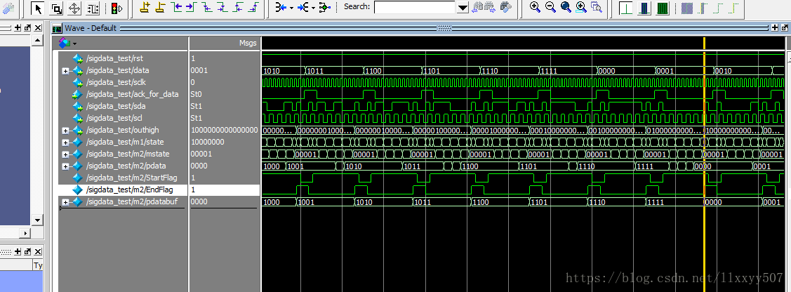
模擬的結果如下:

加入中間變數檢視結果得到如下,可以看出data[3:0]資料準確的傳入到了pdatabuf[3:0],並通過outhigh準確輸出了對應訊號線的高電平。