【OpenGL】Shader例項分析(九)- AngryBots中的主角受傷特效
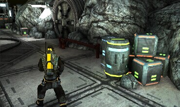
AngryBots是Unity官方的一個非常棒的例子,很有研究價值。以前研究的時候,由於其內容豐富,一時間不知道從哪入手寫文章分析。這一段時間研究shader技術比較多一些,就從shader的這一方面開始吧。首先分析其中的一個螢幕特效:當主角受到攻擊時會出現的全屏效果(postScreenEffect),效果如下:

其實這是一種的Bloom效果,相關檔案有:MobileBloom.js 和 MobileBloom.shader;關於如何檢視這兩個檔案,請參考下圖:
JS程式碼分析
MobileBloom.js部分程式碼如下:
function OnRenderImage (source : RenderTexture, destination : RenderTexture) {
#if UNITY_EDITOR
	FindShaders ();
	CheckSupport ();
	CreateMaterials ();
#endif

	agonyTint = Mathf.Clamp01 (agonyTint - Time.deltaTime * 2.75f);

	var tempRtLowA : RenderTexture = RenderTexture.GetTemporary (source.width / 4, source.height / 4, rtFormat);
	var tempRtLowB : RenderTexture = RenderTexture.GetTemporary (source.width / 4, source.height / 4, rtFormat);

	// prepare data

	apply.SetColor ("_ColorMix", colorMix);
	apply.SetVector ("_Parameter", Vector4 (colorMixBlend * 0.25f,  0.0f, 0.0f, 1.0f - intensity - agonyTint));

	// downsample & blur

	Graphics.Blit (source, tempRtLowA, apply, agonyTint < 0.5f ? 1 : 5);
	Graphics.Blit (tempRtLowA, tempRtLowB, apply, 2);
	Graphics.Blit (tempRtLowB, tempRtLowA, apply, 3);

	// apply

	apply.SetTexture ("_Bloom", tempRtLowA);
	Graphics.Blit (source, destination, apply, QualityManager.quality > Quality.Medium ? 4 : 0);

	RenderTexture.ReleaseTemporary (tempRtLowA);
	RenderTexture.ReleaseTemporary (tempRtLowB);
}
知識點準備
這是一個回撥函式,是MonoBehaviour的生命週期的一部分,每一幀都會被呼叫;當這個函式被呼叫時,所有的3d渲染已經完成,渲染結果以引數source傳入到函式中,後期效果的實現就是對source的處理,並把結果整合到destination中。這個函式所在的指令碼一般繫結在Camera上。此函式只有在Unity Pro版本中才能夠使用。
static void Blit(Texture source, RenderTexture dest);
static void Blit(Texture source, RenderTexture dest, Material mat, int pass = -1);
static void Blit(Texture source, Material mat, int pass = -1);
這個函式就像過轉化器一樣,source圖片經過它的處理變成了dest圖片,其中材質物件mat負責演算法實施(更準確的說法:演算法是繫結到該mat上的shader來實現的。shader可以有多個pass,可以通過pass引數指定特定的shader,-1表示執行這個shader上所有的pass)。
GetTemporary獲取臨時的RenderTexture。ReleaseTemporary用來釋放指定的RenderTexture;
RenderTexture一般在GPU中實現,速度快但資源稀缺。unity內部對RenderTexture做了池化操作,以便複用之。對GetTemporary函式的呼叫其實就是獲取unity中RenderTexture的引用;當處理完之後,使用ReleaseTemporary來釋放對此RenderTexture的引用,達到複用的目的,提高效能。
JS程式碼分析
瞭解了三個知識點,上面程式碼的功能就非常清晰了,分析如下:
- a)獲取兩個渲染貼圖tempRtLowA和tempRtLowB(長寬都是原圖的1/4,用以加快渲染速度)
- b)設定Mat中Shader的引數
- c)通過Mat來處理貼圖,最終渲染到destination貼圖中,用來顯示
- d)釋放臨時的貼圖。
這裡先解釋a和c;
【步驟a】,獲取兩個貼圖,並縮小到原來的1/16(長寬都縮小為原來的1/4,面積為原來的1/16),節約了GPU記憶體,同時提高渲染速度;由於接下來的步驟是對圖片進行模糊處理(對質量要求不高),這樣做是可行的。
【步驟c】(注:呼叫Blit函式來過濾貼圖,其中最後一個數字引數是用來指代shader的pass的)
pass1 或者 pass5, 提取顏色中最亮的部分;pass2 對高亮圖片進行縱向模糊;pass3 對高亮圖片進行橫向模糊;pass0或pass4;把模糊的圖片疊加到原圖片上。
一個亮點,先經過橫向模糊,再經過縱向模糊的過程,如下圖所示(可以把這理解為“使一個點向周圍擴散的演算法”):
圖解演算法
現在的重點是【步驟c】中的shader演算法是怎麼實現的了,先圖解一下演算法:
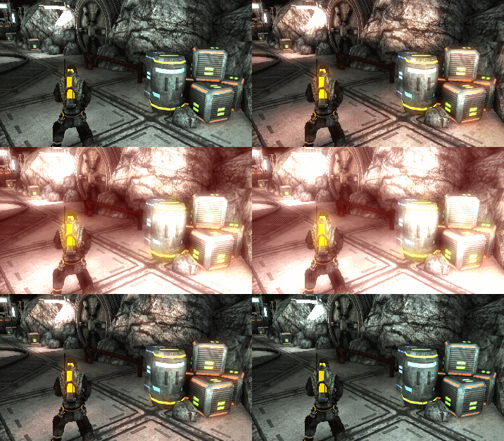
圖1 原圖
圖2【初始化】原圖縮放成原來的1/16
圖3【步驟1】擴大高亮區域
圖4 【步驟2】縱向模糊
圖5 【步驟3】橫向模糊
圖6 【步驟4a】(原圖 + 步驟3的效果)最終疊加的效果,這個效果稱之為glow或者bloom。
圖7 【步驟4b】(原圖 + 步驟3的效果)最終疊加的效果 《===(注意:這個效果需要在步驟1中新增紅色成份)
調節步驟1中的圖片顏色強度,可以形成相應的動畫,如下圖所示:
Shader分析
接下來,我將按照上圖的序列來分析shader開始。
圖3【步驟1】擴大高亮區域
js程式碼:
Graphics.Blit (source, tempRtLowA, apply, 1); struct v2f_withMaxCoords {
half4 pos : SV_POSITION;
half2 uv : TEXCOORD0;
half2 uv2[4] : TEXCOORD1;
};
v2f_withMaxCoords vertMax (appdata_img v)
{
v2f_withMaxCoords o;
o.pos = mul (UNITY_MATRIX_MVP, v.vertex);
o.uv = v.texcoord;
o.uv2[0] = v.texcoord + _MainTex_TexelSize.xy * half2(1.5,1.5);
o.uv2[1] = v.texcoord + _MainTex_TexelSize.xy * half2(-1.5,1.5);
o.uv2[2] = v.texcoord + _MainTex_TexelSize.xy * half2(-1.5,-1.5);
o.uv2[3] = v.texcoord + _MainTex_TexelSize.xy * half2(1.5,-1.5);
return o;
}
fixed4 fragMax ( v2f_withMaxCoords i ) : COLOR
{
fixed4 color = tex2D(_MainTex, i.uv.xy);
color = max(color, tex2D (_MainTex, i.uv2[0]));
color = max(color, tex2D (_MainTex, i.uv2[1]));
color = max(color, tex2D (_MainTex, i.uv2[2]));
color = max(color, tex2D (_MainTex, i.uv2[3]));
return saturate(color - ONE_MINUS_INTENSITY);
}
// 1
Pass {
CGPROGRAM
#pragma vertex vertMax
#pragma fragment fragMax
#pragma fragmentoption ARB_precision_hint_fastest
ENDCG
} 圖4 【步驟2】縱向模糊
js端
Graphics.Blit (tempRtLowA, tempRtLowB, apply, 2);struct v2f_withBlurCoords {
half4 pos : SV_POSITION;
half2 uv2[4] : TEXCOORD0;
};
v2f_withBlurCoords vertBlurVertical (appdata_img v)
{
v2f_withBlurCoords o;
o.pos = mul (UNITY_MATRIX_MVP, v.vertex);
o.uv2[0] = v.texcoord + _MainTex_TexelSize.xy * half2(0.0, -1.5);
o.uv2[1] = v.texcoord + _MainTex_TexelSize.xy * half2(0.0, -0.5);
o.uv2[2] = v.texcoord + _MainTex_TexelSize.xy * half2(0.0, 0.5);
o.uv2[3] = v.texcoord + _MainTex_TexelSize.xy * half2(0.0, 1.5);
return o;
}
fixed4 fragBlurForFlares ( v2f_withBlurCoords i ) : COLOR
{
fixed4 color = tex2D (_MainTex, i.uv2[0]);
color += tex2D (_MainTex, i.uv2[1]);
color += tex2D (_MainTex, i.uv2[2]);
color += tex2D (_MainTex, i.uv2[3]);
return color * 0.25;
}
// 2
Pass {
CGPROGRAM
#pragma vertex vertBlurVertical
#pragma fragment fragBlurForFlares
#pragma fragmentoption ARB_precision_hint_fastest
ENDCG
} 這段程式碼的作用可以描述為:當渲染某一點時,在豎直方向上距其0.5和1.5個單位的四個點(上下各兩個)的顏色疊加起來,作為該點的顏色。結果如圖4所示。
圖5 【步驟3】橫向模糊 (同圖四的描述)
圖6 【步驟4a】最終疊加的效果
(原圖 + 步驟3的效果)最終疊加的效果,這個效果稱之為glow或者bloom。
js段程式碼:
apply.SetTexture ("_Bloom", tempRtLowA);
Graphics.Blit (source, destination, apply, 0);struct v2f_simple {
half4 pos : SV_POSITION;
half4 uv : TEXCOORD0;
};
v2f_simple vertBloom (appdata_img v)
{
v2f_simple o;
o.pos = mul (UNITY_MATRIX_MVP, v.vertex);
o.uv = v.texcoord.xyxy;
#if SHADER_API_D3D9
if (_MainTex_TexelSize.y < 0.0)
o.uv.w = 1.0 - o.uv.w;
#endif
return o;
}
fixed4 fragBloom ( v2f_simple i ) : COLOR
{
fixed4 color = tex2D(_MainTex, i.uv.xy);
return color + tex2D(_Bloom, i.uv.zw);
}
// 0
Pass {
CGPROGRAM
#pragma vertex vertBloom
#pragma fragment fragBloom
#pragma fragmentoption ARB_precision_hint_fastest
ENDCG
} 這段程式碼的作用可以描述為:把圖5的結果疊加到原圖上。結果如圖6所示。
Shader的完整程式碼
MobileBloom.shader:
Shader "Hidden/MobileBloom" {
	Properties {
		_MainTex ("Base (RGB)", 2D) = "white" {}
		_Bloom ("Bloom (RGB)", 2D) = "black" {}
	}

	CGINCLUDE

		#include "UnityCG.cginc"

		sampler2D _MainTex;
		sampler2D _Bloom;

		uniform fixed4 _ColorMix;

		uniform half4 _MainTex_TexelSize;
		uniform fixed4 _Parameter;

		#define ONE_MINUS_INTENSITY _Parameter.w

		struct v2f_simple {
			half4 pos : SV_POSITION;
			half4 uv : TEXCOORD0;
		};

		struct v2f_withMaxCoords {
			half4 pos : SV_POSITION;
			half2 uv : TEXCOORD0;
			half2 uv2[4] : TEXCOORD1;
		};

		struct v2f_withBlurCoords {
			half4 pos : SV_POSITION;
			half2 uv2[4] : TEXCOORD0;
		};

		v2f_simple vertBloom (appdata_img v)
		{
			v2f_simple o;
			o.pos = mul (UNITY_MATRIX_MVP, v.vertex);
        	o.uv = v.texcoord.xyxy;
        	#if SHADER_API_D3D9
        		if (_MainTex_TexelSize.y < 0.0)
        			o.uv.w = 1.0 - o.uv.w;
        	#endif
			return o;
		}

		v2f_withMaxCoords vertMax (appdata_img v)
		{
			v2f_withMaxCoords o;
			o.pos = mul (UNITY_MATRIX_MVP, v.vertex);
        	o.uv = v.texcoord;
        	o.uv2[0] = v.texcoord + _MainTex_TexelSize.xy * half2(1.5,1.5);
			o.uv2[1] = v.texcoord + _MainTex_TexelSize.xy * half2(-1.5,1.5);
			o.uv2[2] = v.texcoord + _MainTex_TexelSize.xy * half2(-1.5,-1.5);
			o.uv2[3] = v.texcoord + _MainTex_TexelSize.xy * half2(1.5,-1.5);
			return o;
		}

		v2f_withBlurCoords vertBlurVertical (appdata_img v)
		{
			v2f_withBlurCoords o;
			o.pos = mul (UNITY_MATRIX_MVP, v.vertex);
        	o.uv2[0] = v.texcoord + _MainTex_TexelSize.xy * half2(0.0, -1.5);
			o.uv2[1] = v.texcoord + _MainTex_TexelSize.xy * half2(0.0, -0.5);
			o.uv2[2] = v.texcoord + _MainTex_TexelSize.xy * half2(0.0, 0.5);
			o.uv2[3] = v.texcoord + _MainTex_TexelSize.xy * half2(0.0, 1.5);
			return o;
		}

		v2f_withBlurCoords vertBlurHorizontal (appdata_img v)
		{
			v2f_withBlurCoords o;
			o.pos = mul (UNITY_MATRIX_MVP, v.vertex);
        	o.uv2[0] = v.texcoord + _MainTex_TexelSize.xy * half2(-1.5, 0.0);
			o.uv2[1] = v.texcoord + _MainTex_TexelSize.xy * half2(-0.5, 0.0);
			o.uv2[2] = v.texcoord + _MainTex_TexelSize.xy * half2(0.5, 0.0);
			o.uv2[3] = v.texcoord + _MainTex_TexelSize.xy * half2(1.5, 0.0);
			return o;
		}

		fixed4 fragBloom ( v2f_simple i ) : COLOR
		{
			fixed4 color = tex2D(_MainTex, i.uv.xy);
			return color + tex2D(_Bloom, i.uv.zw);
		}

		fixed4 fragBloomWithColorMix ( v2f_simple i ) : COLOR
		{
			fixed4 color = tex2D(_MainTex, i.uv.xy);

			half colorDistance = Luminance(abs(color.rgb-_ColorMix.rgb));
			color = lerp(color, _ColorMix, (_Parameter.x*colorDistance));
			color += tex2D(_Bloom, i.uv.zw);

			return color;
		}

		fixed4 fragMaxWithPain ( v2f_withMaxCoords i ) : COLOR
		{
			fixed4 color = tex2D(_MainTex, i.uv.xy);
			color = max(color, tex2D (_MainTex, i.uv2[0]));
			color = max(color, tex2D (_MainTex, i.uv2[1]));
			color = max(color, tex2D (_MainTex, i.uv2[2]));
			color = max(color, tex2D (_MainTex, i.uv2[3]));
			return saturate(color + half4(0.25,0,0,0) - ONE_MINUS_INTENSITY);
		}

		fixed4 fragMax ( v2f_withMaxCoords i ) : COLOR
		{
			fixed4 color = tex2D(_MainTex, i.uv.xy);
			color = max(color, tex2D (_MainTex, i.uv2[0]));
			color = max(color, tex2D (_MainTex, i.uv2[1]));
			color = max(color, tex2D (_MainTex, i.uv2[2]));
			color = max(color, tex2D (_MainTex, i.uv2[3]));
			return saturate(color - ONE_MINUS_INTENSITY);
		}

		fixed4 fragBlurForFlares ( v2f_withBlurCoords i ) : COLOR
		{
			fixed4 color = tex2D (_MainTex, i.uv2[0]);
			color += tex2D (_MainTex, i.uv2[1]);
			color += tex2D (_MainTex, i.uv2[2]);
			color += tex2D (_MainTex, i.uv2[3]);
			return color * 0.25;
		}

	ENDCG

	SubShader {
	  ZTest Always Cull Off ZWrite Off Blend Off
	  Fog { Mode off }

	// 0
	Pass {
		CGPROGRAM

		#pragma vertex vertBloom
		#pragma fragment fragBloom
		#pragma fragmentoption ARB_precision_hint_fastest

		ENDCG
		}
	// 1
	Pass {
		CGPROGRAM

		#pragma vertex vertMax
		#pragma fragment fragMax
		#pragma fragmentoption ARB_precision_hint_fastest

		ENDCG
		}
	// 2
	Pass {
		CGPROGRAM

		#pragma vertex vertBlurVertical
		#pragma fragment fragBlurForFlares
		#pragma fragmentoption ARB_precision_hint_fastest

		ENDCG
		}
	// 3
	Pass {
		CGPROGRAM

		#pragma vertex vertBlurHorizontal
		#pragma fragment fragBlurForFlares
		#pragma fragmentoption ARB_precision_hint_fastest

		ENDCG
		}
	// 4
	Pass {
		CGPROGRAM

		#pragma vertex vertBloom
		#pragma fragment fragBloomWithColorMix
		#pragma fragmentoption ARB_precision_hint_fastest

		ENDCG
		}
	// 5
	Pass {
		CGPROGRAM

		#pragma vertex vertMax
		#pragma fragment fragMaxWithPain
		#pragma fragmentoption ARB_precision_hint_fastest

		ENDCG
		}
	}
	FallBack Off
}
參考文獻
《Unity Shaders and Effects Cookbook》的章節:


