
[latex]使用tikz畫流程圖
本文講述使用tikz巨集包畫流程圖的方法。
\usepackage{tikz}
\usetikzlibrary{arrows,shapes,chains}與圖片相同,也是包含在\begin{figure}…\end{figure}中。
繪製流程圖一共分為兩個步驟,步驟一是定義控制元件樣式。
給一個例子,定義一個矩形框:
\tikzstyle{ process } = [rectangle, minimum width = 3cm, minimum height = 1cm, text centered, draw = black]ID為process,型別為rectangle,最小寬度3cm,最小高度1cm,文字居中,顏色為black。此處定義最小寬高是因為,該控制元件定義後實際運用中,寬高是可變的。
再給一個定義箭頭的例子,意義相似,其中->表示箭頭,–表示直線:
\tikzstyle{ arrow2 } = [thick, ->, >= stealth]所有的控制元件都需要先定義再使用,包括矩形、平行四邊形等形狀以及直線、箭頭等連線符都要預先定義。
在定義控制元件結束後,在\begin{ tikzpicture }[node distance = 1.5cm] … \end{ tikzpicture }中放置控制元件。其中node distance = 1.5cm表示流程圖中每個框的間距預設為1.5cm。給一個放置控制元件的例子。
\node (in1) [ 第一行表示放置控制元件,控制元件名為in1,控制元件型別為io,在前面定義。此為第一個控制元件,無需指明放置位置。後面大括號中為空,表示其中沒有文字。
第二行放置第二個控制元件,控制元件名為pro1,控制元件型別為startstop,放置位置為在in1的下方。前面指明預設間距為1.5cm,則實際位置為pro1放置在in1下方1.5cm處。其中文字為線性濾波,\small
第三行放置第三個控制元件,控制元件名為in2,在in1左邊,預設間距為1.5cm,但有xshift=-2.5cm,這樣in2就放置在in1的左邊4cm處。其中文字為亮度。
第四行表示放置文字,在(-1.5,0)位置,文字是輸入影象。
在放置完成控制元件以後,開始放置連線。
\draw[arrow](pro1) -- (in1);表示連線,線條樣式為arrow,在前面定義,連線pro1和in1。
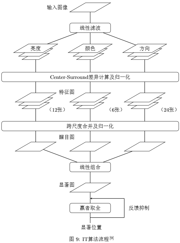
最後給一個流程圖的例子。流程圖的原圖來自於Itti的顯著性論文。裡面基本包含了常用流程圖畫法中的所有要點。
Latex程式碼
\begin{ figure }[htb]
\centering
%定義形狀樣式
\tikzstyle{ startstop } = [rectangle, rounded corners, minimum width = 3cm, minimum height = 0.7cm, text centered, draw = black]
\tikzstyle{ startstop2 } = [rectangle, rounded corners, minimum width = 13cm, minimum height = 0.7cm, text centered, draw = black]
\tikzstyle{ io } = [trapezium, trapezium left angle = 30, trapezium right angle = 150, minimum width = 3cm, text centered, draw = black, fill = white]
\tikzstyle{ io2 } = [trapezium, trapezium left angle = 30, trapezium right angle = 150, minimum width = 2.5cm, draw = black, fill = white]
\tikzstyle{ io3 } = [trapezium, trapezium left angle = 30, trapezium right angle = 150, minimum width = 2cm, draw = black, fill = white]
\tikzstyle{ process } = [rectangle, minimum width = 3cm, minimum height = 1cm, text centered, draw = black]
\tikzstyle{ decision } = [diamond, minimum width = 3cm, minimum height = 1cm, text centered, draw = black]
\tikzstyle{ arrow } = [thick, -, >= stealth]
\tikzstyle{ arrow2 } = [thick, ->, >= stealth]

\begin{ tikzpicture }[node distance = 1.5cm]
% 定義流程圖具體形狀
\coordinate[label = left:{\small 輸入影象}](A) at(-1.5, 0);
\node(in1) [io] {};
\node(pro1) [startstop, below of = in1] {\small 線性濾波};

\node(in2 - 2)[io3, below of = pro1, yshift = -0.6cm]{};
\node(in3 - 2)[io3, left of = in2 - 2, xshift = -2.5cm]{};
\node(in4 - 2)[io3, right of = in2 - 2, xshift = 2.5cm]{};

\node(in2 - 1)[io2, below of = pro1, yshift = -0.3cm]{};
\node(in3 - 1)[io2, left of = in2 - 1, xshift = -2.5cm]{};
\node(in4 - 1)[io2, right of = in2 - 1, xshift = 2.5cm]{};

\node(in2) [io, below of = pro1] {\small 顏色};
\node(in3)[io, left of = in2, xshift = -2.5cm]{ \small 亮度 };
\node(in4)[io, right of = in2, xshift = 2.5cm]{ \small 方向 };

\node(in5)[startstop2, below of = in2 - 2]{ \small Center - Surround差異計算及歸一化 };

\node(in6 - 2)[io3, below of = in5, yshift = -0.6cm]{};
\node(in7 - 2)[io3, left of = in6 - 2, xshift = -2.5cm]{};
\node(in8 - 2)[io3, right of = in6 - 2, xshift = 2.5cm]{};

\node(in6 - 1)[io2, below of = in5, yshift = -0.3cm]{};
\node(in7 - 1)[io2, left of = in6 - 1, xshift = -2.5cm]{};
\node(in8 - 1)[io2, right of = in6 - 1, xshift = 2.5cm]{};

\node(in6) [io, below of = in5] {};
\node(in7)[io, left of = in6, xshift = -2.5cm]{};
\node(in8)[io, right of = in6, xshift = 2.5cm]{};

\coordinate[label = left:{\small 特徵圖}](B) at(-1, -6.2);
\coordinate[label = left:{\small (12張)}](C) at(-1.5, -7.5);
\coordinate[label = left:{\small (6張)}](D) at(2.7, -7.5);
\coordinate[label = left:{\small (24張)}](E) at(6.7, -7.5);

\node(in9)[startstop2, below of = in6 - 2]{ \small 跨尺度合併及歸一化 };

\node(in10) [io, below of = in9] {};
\node(in11)[io, left of = in10, xshift = -2.5cm]{};
\node(in12)[io, right of = in10, xshift = 2.5cm]{};

\coordinate[label = left:{\small 醒目圖}](F) at(-1, -9.5);
\node(in13) [startstop, below of = in10] {\small 線性組合};
\node(in14) [io, below of = in13] {};
\coordinate[label = left:{\small 顯著圖}](G) at(-1, -13);

\node(in15) [startstop, below of = in14] {\small 贏者取全};
\coordinate[label = left:{\small 顯著位置}]() at(1, -16.1);
\coordinate[label = left:{\small 反饋抑制}]() at(4.5, -14.7);

%連線
\draw[arrow](pro1) -- (in1);
\draw[arrow](pro1) -- (in2);
\draw[arrow](pro1) -- (in3);
\draw[arrow](pro1) -- (in4);
\draw[arrow](0, -4.75) -- (in2 - 2);
\draw[arrow](-4, -4.75) -- (in3 - 2);
\draw[arrow](4, -4.75) -- (in4 - 2);
\draw[arrow](0, -5.45) -- (in6);
\draw[arrow](-4, -5.45) -- (in7);
\draw[arrow](4, -5.45) -- (in8);
\draw[arrow](0, -8.35) -- (in6 - 2);
\draw[arrow](-4, -8.35) -- (in7 - 2);
\draw[arrow](4, -8.35) -- (in8 - 2);
\draw[arrow](0, -9.05) -- (in10);
\draw[arrow](-4, -9.05) -- (in11);
\draw[arrow](4, -9.05) -- (in12);
\draw[arrow](in13) -- (in10);
\draw[arrow](in13) -- (in11);
\draw[arrow](in13) -- (in12);
\draw[arrow](in13) -- (in14);
\draw[arrow](in14) -- (in15);
\draw[arrow](in15) -- (0, -15.8);
\draw[arrow](0, -15.4) -- (2.5, -15.4);
\draw[arrow](2.5, -14) -- (2.5, -15.4);
\draw[arrow2](2.5, -14) -- (0, -14);
\end{ tikzpicture }
\caption{ IT演算法流程\cite{ Itti } }
\end{ figure }