
WebGPU學習(八):學習“texturedCube”示例
大家好,本文學習Chrome->webgpu-samplers->texturedCube示例。
上一篇博文:
WebGPU學習(七):學習“twoCubes”和“instancedCube”示例
學習texturedCube.ts
最終渲染結果:

該示例繪製了有一個紋理的立方體。
與“rotatingCube”示例相比,該示例增加了下面的步驟:
- 傳輸頂點的uv資料
- 增加了sampler和sampled-texture型別的uniform資料
下面,我們開啟texturedCube.ts檔案,依次分析增加的步驟:
傳遞頂點的uv資料
- shader加入uv attribute
程式碼如下:
  const vertexShaderGLSL = `#version 450
  ...
  layout(location = 0) in vec4 position;
  layout(location = 1) in vec2 uv;

  layout(location = 0) out vec2 fragUV;
  layout(location = 1) out vec4 fragPosition;

  void main() {
    fragPosition = 0.5 * (position + vec4(1.0));
    ...
    fragUV = uv;
  }
  `;

  const fragmentShaderGLSL = `#version 450
  layout(set = 0, binding = 1) uniform sampler mySampler;
  layout(set = 0, binding = 2) uniform texture2D myTexture;

  layout(location = 0) in vec2 fragUV;
  layout(location = 1) in vec4 fragPosition;
  layout(location = 0) out vec4 outColor;

  void main() {
    outColor =  texture(sampler2D(myTexture, mySampler), fragUV) * fragPosition;
  }
  `;
vertex shader傳入了uv attribute資料,並將其傳遞給fragUV,從而傳到fragment shader,作為紋理取樣座標
另外,這裡可以順便說明下:fragPosition用來實現與position相關的顏色漸變效果
- uv資料包含在verticesBuffer的cubeVertexArray中
cubeVertexArray的程式碼如下:
cube.ts:
export const cubeUVOffset = 4 * 8;
export const cubeVertexArray = new Float32Array([
    // float4 position, float4 color, float2 uv,
    1, -1, 1, 1,   1, 0, 1, 1,  1, 1,
    -1, -1, 1, 1,  0, 0, 1, 1,  0, 1,
    -1, -1, -1, 1, 0, 0, 0, 1,  0, 0,
    1, -1, -1, 1,  1, 0, 0, 1,  1, 0,
    1, -1, 1, 1,   1, 0, 1, 1,  1, 1,
    -1, -1, -1, 1, 0, 0, 0, 1,  0, 0,

    ...
]);
建立和設定verticesBuffer的相關程式碼如下:
texturedCube.ts:
  const verticesBuffer = device.createBuffer({
    size: cubeVertexArray.byteLength,
    usage: GPUBufferUsage.VERTEX | GPUBufferUsage.COPY_DST
  });
  verticesBuffer.setSubData(0, cubeVertexArray);

  ...

  return function frame() {
    ...
    passEncoder.setVertexBuffer(0, verticesBuffer);
    ...
} - 建立render pipeline時指定uv attribute的相關資料
程式碼如下:
  const pipeline = device.createRenderPipeline({
    ...
    vertexState: {
      vertexBuffers: [{
        ...
        attributes: [
        ...
        {
          // uv
          shaderLocation: 1,
          offset: cubeUVOffset,
          format: "float2"
        }]
      }],
    },
    ...
  });
增加了sampler和sampled-texture型別的uniform資料
WebGPU相對於WebGL1,提出了sampler,可以對它設定filter、wrap等引數,從而實現了texture和sampler自由組合,同一個texture能夠以不同filter、wrap來取樣
- fragment shader傳入這兩個uniform資料,用於紋理取樣
程式碼如下:
  const fragmentShaderGLSL = `#version 450
  layout(set = 0, binding = 1) uniform sampler mySampler;
  layout(set = 0, binding = 2) uniform texture2D myTexture;

  layout(location = 0) in vec2 fragUV;
  layout(location = 1) in vec4 fragPosition;
  layout(location = 0) out vec4 outColor;

  void main() {
    outColor =  texture(sampler2D(myTexture, mySampler), fragUV) * fragPosition;
  }
`;- 建立bind group layout時指定它們在shader中的binding位置等引數
程式碼如下:
  const bindGroupLayout = device.createBindGroupLayout({
    bindings: [
    ...
    {
      // Sampler
      binding: 1,
      visibility: GPUShaderStage.FRAGMENT,
      type: "sampler"
    }, {
      // Texture view
      binding: 2,
      visibility: GPUShaderStage.FRAGMENT,
      type: "sampled-texture"
    }]
});- 拷貝圖片到texture,返回texture
程式碼如下,後面會進一步研究:
const cubeTexture = await createTextureFromImage(device, 'assets/img/Di-3d.png', GPUTextureUsage.SAMPLED);- 建立sampler,指定filter
程式碼如下:
  const sampler = device.createSampler({
    magFilter: "linear",
    minFilter: "linear",
  });
我們看一下相關定義:
GPUSampler createSampler(optional GPUSamplerDescriptor descriptor = {});

...

dictionary GPUSamplerDescriptor : GPUObjectDescriptorBase {
    GPUAddressMode addressModeU = "clamp-to-edge";
    GPUAddressMode addressModeV = "clamp-to-edge";
    GPUAddressMode addressModeW = "clamp-to-edge";
    GPUFilterMode magFilter = "nearest";
    GPUFilterMode minFilter = "nearest";
    GPUFilterMode mipmapFilter = "nearest";
    float lodMinClamp = 0;
    float lodMaxClamp = 0xffffffff;
    GPUCompareFunction compare = "never";
};
GPUSamplerDescriptor的addressMode指定了texture在u、v、w方向的wrap mode(u、v方向的wrap相當於WebGL1的wrapS、wrapT)(w方向是給3d texture用的)
mipmapFilter與mipmap有關,lodXXX與texture lod有關,compare與軟陰影的Percentage Closer Filtering技術有關,我們不討論它們
- 建立uniform bind group時傳入sampler和texture的view
  const uniformBindGroup = device.createBindGroup({
    layout: bindGroupLayout,
    bindings: [
    ...
    {
      binding: 1,
      resource: sampler,
    }, {
      binding: 2,
      resource: cubeTexture.createView(),
    }],
  });
參考資料
Sampler Object
詳細分析“拷貝圖片到texture”步驟
相關程式碼如下:
const cubeTexture = await createTextureFromImage(device, 'assets/img/Di-3d.png', GPUTextureUsage.SAMPLED);該步驟可以分解為兩步:
1.解碼圖片
2.拷貝解碼後的型別為HTMLImageElement的圖片到GPU的texture中
下面依次分析:
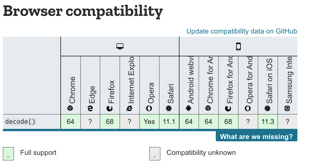
解碼圖片
開啟helper.ts檔案,檢視createTextureFromImage對應程式碼:
  const img = document.createElement('img');
  img.src = src;
  await img.decode();
這裡使用decode api來解碼圖片,也可以使用img.onload來實現:
  const img = document.createElement('img');
  img.src = src;
  img.onload = (img) => {
    ...
  };
根據Pre-Loading and Pre-Decoding Images with Javascript for Better Performance的說法,圖片的載入過程有兩個步驟:
1.從伺服器載入圖片
2.解碼圖片
第1步都是在其它執行緒上並行執行;
如果用onload,則瀏覽器會在主執行緒上同步執行第2步,會阻塞主執行緒;
如果用decode api,則瀏覽器會在其它執行緒上並行執行第2步,不會阻塞主執行緒。
chrome和firefox瀏覽器都支援decode api,因此載入圖片應該優先使用該API:
參考資料
Pre-Loading and Pre-Decoding Images with Javascript for Better Performance
Chrome 圖片解碼與 Image.decode API
拷貝圖片
WebGL1直接使用texImage2D將圖片上傳到GPU texture中,而WebGPU能讓我們更加靈活地控制上傳過程。
WebGPU有兩種方法上傳:
- 建立圖片對應的imageBitmap,將其拷貝到GPU texture中
該方法要用到copyImageBitmapToTexture函式。雖然WebGPU規範已經定義了該函式,但目前Chrome Canary不支援它,所以暫時不能用該方法上傳。
參考資料
Proposal for copyImageBitmapToTexture
ImageBitmapToTexture design
- 將圖片繪製到canvas中,通過getImageData獲得資料->將其設定到buffer中->把buffer資料拷貝到GPU texture中
我們來看下createTextureFromImage對應程式碼:
  const imageCanvas = document.createElement('canvas');
  imageCanvas.width = img.width;
  imageCanvas.height = img.height;

  const imageCanvasContext = imageCanvas.getContext('2d');

  //flipY
  imageCanvasContext.translate(0, img.height);
  imageCanvasContext.scale(1, -1);

  imageCanvasContext.drawImage(img, 0, 0, img.width, img.height);
  const imageData = imageCanvasContext.getImageData(0, 0, img.width, img.height);
這裡建立canvas->繪製圖片->獲得圖片資料。
(注:在繪製圖片時將圖片在Y方向反轉了)
接著看程式碼:
  let data = null;

  const rowPitch = Math.ceil(img.width * 4 / 256) * 256;
  if (rowPitch == img.width * 4) {
    data = imageData.data;
  } else {
    data = new Uint8Array(rowPitch * img.height);
    for (let y = 0; y < img.height; ++y) {
      for (let x = 0; x < img.width; ++x) {
        let i = x * 4 + y * rowPitch;
        data[i] = imageData.data[i];
        data[i + 1] = imageData.data[i + 1];
        data[i + 2] = imageData.data[i + 2];
        data[i + 3] = imageData.data[i + 3];
      }
    }
  }

  const texture = device.createTexture({
    size: {
      width: img.width,
      height: img.height,
      depth: 1,
    },
    format: "rgba8unorm",
    usage: GPUTextureUsage.COPY_DST | usage,
  });

  const textureDataBuffer = device.createBuffer({
    size: data.byteLength,
    usage: GPUBufferUsage.COPY_DST | GPUBufferUsage.COPY_SRC,
  });

  textureDataBuffer.setSubData(0, data);
rowPitch需要為256的倍數(也就是說,圖片的寬度需要為64px的倍數),這是因為Dx12對此做了限制(參考Copies investigation):
RowPitch must be aligned to D3D12_TEXTURE_DATA_PITCH_ALIGNMENT.
Offset must be aligned to D3D12_TEXTURE_DATA_PLACEMENT_ALIGNMENT, which is 512.
另外,關於紋理尺寸,可以參考WebGPU-6:
第一個問題是關於紋理尺寸的,回答是WebGPU沒有對尺寸有特別明確的要求。sample code中最多不能比4kor8k大就行。這個也不是太難理解,OpenGL對紋理和FBO的尺寸總是有上限的。
根據我的測試,buffer(程式碼中的textureDataBuffer)中的圖片資料需要為未壓縮的圖片資料(它的型別為Uint8Array,length=img.width * img.height * 4(因為每個畫素有r、g、b、a這4個值)),否則會報錯(在我的測試中,“通過canvas->toDataURL得到圖片的base64->將其轉為Uint8Array,得到壓縮後的圖片資料->將其設定到buffer中”會報錯)
繼續看程式碼:
  const commandEncoder = device.createCommandEncoder({});
  commandEncoder.copyBufferToTexture({
    buffer: textureDataBuffer,
    rowPitch: rowPitch,
    imageHeight: 0,
  }, {
    texture: texture,
  }, {
    width: img.width,
    height: img.height,
    depth: 1,
  });

  device.defaultQueue.submit([commandEncoder.finish()]);

  return texture;
這裡提交了copyBufferToTexture這個command到GPU,並返回texture
(注:這個command此時並沒有執行,會由GPU決定什麼時候執行)
WebGPU支援buffer與buffer、buffer與texture、texture與texture之間互相拷貝。
參考資料
3 channel formats
Copies investigation (+ proposals)
參考資料
WebGPU規範
webgpu-samplers Github Repo
WebGP