
1.3 Vrep例程之BubbleRob擴充套件(循跡移動)
文章目錄
擴充套件例程1.1的BubbleRob使得小車能沿設定路線移動,最終效果圖

建立視覺感測器
- 首先建立要放在BubbleRob上的三個視覺感測器,即 [Menu bar --> Add --> Vision sensor --> Orthographic type],然後修改其性質,如圖

- 當然,為了循跡,每個視覺感測器都要面向地面,則設定它們姿態,即在姿態對話方塊中設定 [180;0;0] for the Alpha-Beta-Gamma items
- 下面要讀取視覺感測器資料,我們這裡的情況較簡單,因為我們視覺感測器只有one pixel,所以我們只要查詢視覺感測器所讀到影象的平均強度值就行了。對於複雜情況,要設定感測器的filters。
We have several possibilities to read a vision sensor. Since our vision sensor has just one pixel and operates in an easy way, we will simply query the average intensity value of the image read by our vision sensor. For more complex cases, we could have set-up several vision sensor filters.
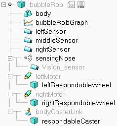
接著,修改層次樹,attach三個視覺感測器,如圖
接著設定三個視覺感測器的位置,按如下絕對座標設定
left sensor: [0.2;0.042;0.018]
middle sensor: [0.2;0;0.018]
right sensor: [0.2;-0.042;0.018]
設定路徑
具體操作:[Menu bar --> Add --> Path --> Circle type],接著我們有兩種方法調整路徑
- Ctrl+選擇控制點,拖拽
- 進入path編輯模式,有更高的靈活性(推薦)

搞掂path形狀,接著uncheck Show orientation of points, Show path line and Show current position on path (在path properties中)接著點選 Show path shaping dialog,這將會開啟path shaping對話方塊.,點選 Path shaping enabled,設定type為horizontal segmen以及Scaling factor為 4.0,最後一步為了避免Z軸衝突(floor的Z軸位置與path的Z軸位置衝突,影響視覺感測器結果),所以將path的Z軸向上提0.5mm
繫結指令碼
指令碼定義小車循跡行為,建立一個child script,程式碼如下
function speedChange_callback(ui,id,newVal)
    speed=minMaxSpeed[1]+(minMaxSpeed[2]-minMaxSpeed[1])*newVal/100
end

function sysCall_init()
    -- This is executed exactly once, the first time this script is executed
    bubbleRobBase=sim.getObjectAssociatedWithScript(sim.handle_self)
    leftMotor=sim.getObjectHandle("leftMotor")
    rightMotor=sim.getObjectHandle("rightMotor")
    noseSensor=sim.getObjectHandle("sensingNose")
    minMaxSpeed={50*math.pi/180,300*math.pi/180}
    backUntilTime=-1 -- Tells whether bubbleRob is in forward or backward mode
    floorSensorHandles={-1,-1,-1}
    floorSensorHandles[1]=sim.getObjectHandle("leftSensor")
    floorSensorHandles[2]=sim.getObjectHandle("middleSensor")
    floorSensorHandles[3]=sim.getObjectHandle("rightSensor")
    -- Create the custom UI:
        xml = '<ui title="'..sim.getObjectName(bubbleRobBase)..' speed" closeable="false" resizeable="false" activate="false">'..[[
        <hslider minimum="0" maximum="100" onchange="speedChange_callback" id="1"/>
        <label text="" style="* {margin-left: 300px;}"/>
        </ui>
        ]]
    ui=simUI.reate(xml)
    speed=(minMaxSpeed[1]+minMaxSpeed[2])*0.5
    simUI.setSliderValue(ui,1,100*(speed-minMaxSpeed[1])/(minMaxSpeed[2]-minMaxSpeed[1]))
end

function sysCall_actuation()
    result=sim.readProximitySensor(noseSensor)
    if (result>0) then backUntilTime=sim.getSimulationTime()+4 end

    -- read the line detection sensors:
    sensorReading={false,false,false}
    for i=1,3,1 do
        result,data=sim.readVisionSensor(floorSensorHandles[i])
        if (result>=0) then
            sensorReading[i]=(data[11]<0.3) -- data[11] is the average of intensity of the image
        end
        print(sensorReading[i])
    end

    -- compute left and right velocities to follow the detected line:
    rightV=speed
    leftV=speed
    if sensorReading[1] then
        leftV=0.03*speed
    end
    if sensorReading[3] then
        rightV=0.03*speed
    end
    if sensorReading[1] and sensorReading[3] then
        backUntilTime=sim.getSimulationTime()+2
    end

    if (backUntilTime<sim.getSimulationTime()) then
        -- When in forward mode, we simply move forward at the desired speed
        sim.setJointTargetVelocity(leftMotor,leftV)
        sim.setJointTargetVelocity(rightMotor,rightV)
    else
        -- When in backward mode, we simply backup in a curve at reduced speed
        sim.setJointTargetVelocity(leftMotor,-speed/2)
        sim.setJointTargetVelocity(rightMotor,-speed/8)
    end
end

function sysCall_cleanup()
	simUI.destroy(ui)
end
此外,在除錯過程中可將視覺感測器的檢視與floating view繫結,便於觀察