
TensorFlow的圖切割模組——Graph Partitioner
阿新 • • 發佈:2018-12-16
背景
[作者: DeepLearningStack,阿里巴巴演算法工程師] 在經過TensorFlow的 Placer策略模組調整之後,下一步就是根據Placement資訊對Graph做切割,然後分發到不同的Device上去執行的過程了。在對Graph做切割時,為了保證跨Device執行的邏輯與切割前一致並保證原圖中Node節點之間的依賴關係不受到破壞,不但需要插入Send、Recv通訊節點對,還需要維護相對複雜的Control Edge。這些功能被設計在了TensorFlow的Graph Partitioner模組中。從該模組的程式碼量和原理上看,其內容非常好理解,但在涉及到對含有while_loop、loop_contition、exit、enter、merge、switch等Control Flow Op的圖做切割時,其處理就顯得相對複雜。本篇主要介紹Graph Partitioner的整體過程和相關原始碼,但考慮到Control Flow Op相關的處理還需要一些前置知識,而這些前置知識在TensorFlow原始碼閱讀與架構梳理系列中尚未完成書寫,因此本篇暫時過濾掉對Control Flow Op相關邏輯的處理。功能描述
Graph Partition切割流程
為了描述方便,特意將圖切割過程分為以下幾個子過程,整體流程如下圖所示,圖右邊的文字是對每個過程的簡短描述,本篇我們重點闡述標記為深色的子過程。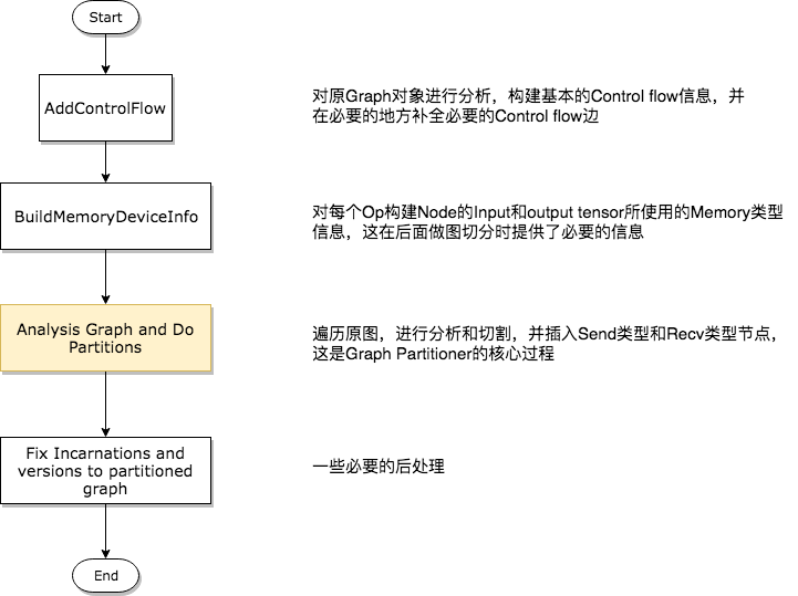
第一步——分析構建Control Flow相關資訊
 1 GraphInfo g_info;
 2 if (!opts.control_flow_added) {
 3   // Add the "code" for distributed execution of control flow. Code is
 4   // added only for the frames that are placed on multiple devices. The
 5   // new graph is an equivalent transformation of the original graph and
 6   // has the property that it can be subsequently partitioned arbitrarily
 7   // (down to the level of individual device) for distributed execution.
 8   status = AddControlFlow(opts, g, &g_info);
 9   if (!status.ok()) return status;
10 }
第二步——構建Op的Input和Output Memory型別資訊
在介紹這個過程之前,首先需要明確兩種概念,他們是DeviceMemory和HostMemory。前者指的是計算裝置的Memory型別,後者指的是CPU的Memory型別,它們在TensorFlow中被定義為Enum型別,程式碼如下所示。1 // MemoryType is used to describe whether input or output Tensors of 2 // an OpKernel should reside in "Host memory" (e.g., CPU memory) or 3 // "Device" Memory (CPU memory for CPU devices, GPU memory for GPU 4 // devices). 5 enum MemoryType { 6 DEVICE_MEMORY = 0, 7 HOST_MEMORY = 1, 8 };對Op的Input和Output Memory資訊進行檢索並構建快取的函式是BuildMemoryDeviceInfo,該過程構建的資訊對後面真正做圖切割非常重要。因為TensorFlow的Op在註冊時需要不但需要指定其在各個Device上的實現版本(比如CPU版本的Op和GPU版本的Op都是分別註冊到系統中的),還需要指出其Input和Output Tensor的型別以及所使用的Memory型別,即使某個Op存在GPU上的實現,它的GPU版本也有可能需要在CPU上讀入資料或輸出結果。例如,GPU版本的Reshape Op註冊程式碼如下。
 1 #define REGISTER_GPU_KERNEL(type)                               \
 2   REGISTER_KERNEL_BUILDER(Name("Reshape")                       \
 3                               .Device(DEVICE_GPU)               \
 4                               .HostMemory("shape")              \
 5                               .TypeConstraint<type>("T")        \
 6                               .TypeConstraint<int32>("Tshape"), \
 7                           ReshapeOp);                           \
 8   REGISTER_KERNEL_BUILDER(Name("Reshape")                       \
 9                               .Device(DEVICE_GPU)               \
10                               .HostMemory("shape")              \
11                               .TypeConstraint<type>("T")        \
12                               .TypeConstraint<int64>("Tshape"), \
13                           ReshapeOp);
上面的巨集顯示,雖然Reshape Op確實在GPU上有註冊的實現版本,但是它依然要使用HostMemory。另外,某些Tensor的型別也決定了其是否可以被放置到Device Memory上,一般情況下float型別的資料對於計算裝置是非常友好的,而String型別就不是這樣,所以在types.cc檔案中規定了一些強制被放在HostMemory的資料型別,如下程式碼所示。
 1 bool DataTypeAlwaysOnHost(DataType dt) {
 2   // Includes DT_STRING and DT_RESOURCE.
 3   switch (dt) {
 4     case DT_STRING:
 5     case DT_STRING_REF:
 6     case DT_RESOURCE:
 7       return true;
 8     default:
 9       return false;
10   }
11 }
TensorFlow的設計哲學認為,參與計算的Tensor應該被放在DeviceMemory上,而參與控制的Tensor應該放在HostMemory上。這樣的設計思路雖然有一定道理,但也確實對一些case產生了負面的效能影響。在後面的過程中我們可以看到,Partition過程會根據每個Op的Input和Output Memory型別決定是否插入Send類和Recv類節點對,因此會經常遇到處於同一個Device上的兩個節點也需要插入Send類和Recv類節點對的情況,顯然這有可能帶來效能下降。
第三步——對原圖進行分析,併產出切割後的多個子圖
在面兩個步驟的準備工作完成之後,就可以進行圖切割和Send類、Recv類節點對的插入,以及Control Edge的插入了,這個過程如下圖所示。因為流程圖繪製的比較簡潔,我們將在下面對該圖進行詳細說明。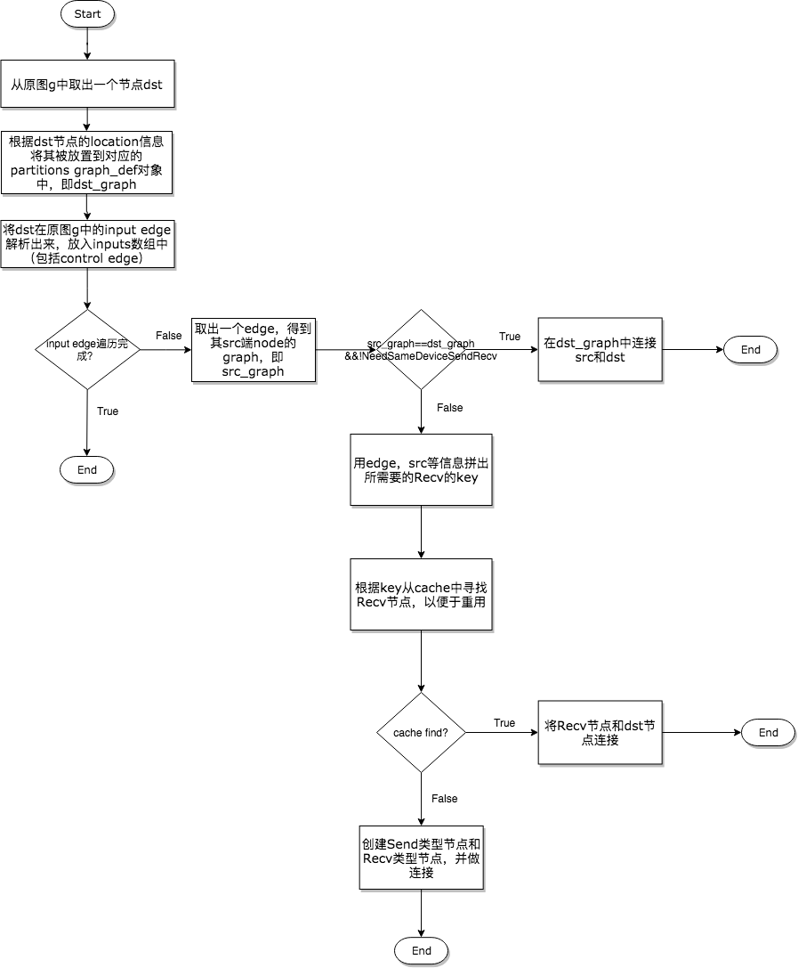 1.將原圖中取出一個節點dst,根據其Device將其分配到對應的Sub Graph中,然後以dst節點為終點節點,沿著其接收Tensor的方向向輸入節點src進行分析;
2.Node之間的連線依靠的是Edge,因此對於dst來說需要根據其Input的Edge來分析src節點的位置,所以這裡要獲得dst的所有Input Edge;
3.在逐個遍歷分析Input Edge時,第一個要處理的就是src和dst處於同一個Device,但依然需要插入Send類和Recv類節點對的情況。根據第二步BuildMemoryDeviceInfo提供的資訊,某些Op的註冊和特殊之處確實會得到這種情況;
4.如果決定需要插入Send類和Recv類節點對,那麼優先考慮是否可以重用Recv節點,如果根據資訊拼出的Key能夠在快取中搜索到該Recv Node,那麼則取出重用。這種Recv Fusion是一種效能優化手段,能避免多次不必要的通訊,真正做到達到一次通訊多次使用的目的,下面的程式碼展示了這一個過程;
1.將原圖中取出一個節點dst,根據其Device將其分配到對應的Sub Graph中,然後以dst節點為終點節點,沿著其接收Tensor的方向向輸入節點src進行分析;
2.Node之間的連線依靠的是Edge,因此對於dst來說需要根據其Input的Edge來分析src節點的位置,所以這裡要獲得dst的所有Input Edge;
3.在逐個遍歷分析Input Edge時,第一個要處理的就是src和dst處於同一個Device,但依然需要插入Send類和Recv類節點對的情況。根據第二步BuildMemoryDeviceInfo提供的資訊,某些Op的註冊和特殊之處確實會得到這種情況;
4.如果決定需要插入Send類和Recv類節點對,那麼優先考慮是否可以重用Recv節點,如果根據資訊拼出的Key能夠在快取中搜索到該Recv Node,那麼則取出重用。這種Recv Fusion是一種效能優化手段,能避免多次不必要的通訊,真正做到達到一次通訊多次使用的目的,下面的程式碼展示了這一個過程;
 1       // Check whether there is already a send/recv pair transferring
 2       // the same tensor/control from the src to dst partition.
 3       const bool on_host = IsDstInputOnHost(edge, g_info);
 4       DupRecvKey key{src->id(), edge->src_output(), dst_graph, on_host};
 5       auto iter = dup_recv.find(key);
 6       if (iter != dup_recv.end()) {
 7         // We found one. Reuse the data/control transferred already.
 8         const string& recv_node_name = iter->second.recv->name();
 9         if (edge->IsControlEdge()) {
10           AddInput(dst_def, recv_node_name, Graph::kControlSlot);
11         } else {
12           AddInput(dst_def, recv_node_name, 0);
13         }
14         ref_control_inputs.push_back(recv_node_name);
15
16         // We want the start_time for the recv to be the smallest of the start
17         // times of it's consumers. So we update this whenever we use a recv,
18         // and write it out to the attribute at the end of the subroutine
19         if (iter->second.start_time > recv_start_time) {
20           iter->second.start_time = recv_start_time;
21         }
22         continue;
23       }
5.如果快取中沒有找到可重用的節點,那麼只能建立新的Send類和Recv類節點對了。插入通訊節點對時需要考慮多種情況,有時插入Send和Recv節點就能完成任務,有時還需要插入Control Edge以保證依賴順序,有時甚至還要插入一些其他的輔助節點。事實上,分成這三種邏輯處理已經覆蓋任何情況了,後面一章將詳細闡述這三種處理邏輯。 第四步——必要的後處理 這是一些收尾的工作,過程非常簡單,比如完善Send和Recv節點的Incarnation資訊,補全各個子圖的version資訊等,程式碼如下所示。
 1   const FunctionLibraryDefinition* flib_def = opts.flib_def;
 2   if (flib_def == nullptr) {
 3     flib_def = &g->flib_def();
 4   }
 5
 6   // Set versions, function library and send/recv incarnation.
 7   for (auto& it : *partitions) {
 8     GraphDef* gdef = &it.second;
 9     *gdef->mutable_versions() = g->versions();
10     // Prune unreachable functions from `flib_def` before adding them to `gdef`.
11     *gdef->mutable_library() = flib_def->ReachableDefinitions(*gdef).ToProto();
12
13     // Traverse the graph to fill every send/recv op's incarnation
14     // information.
15     SetIncarnation(opts, gdef);
16   }
Send和Recv節點對插入的三種情況
在程式碼中,宣告插入Send和Recv節點的程式碼段非常簡單,如下所示。
 1       // Need to split edge by placing matching send/recv nodes on
 2       // the src/dst sides of the edge.
 3       NodeDef* send = AddSend(opts, g_info, src_graph, edge, send_from,
 4                               send_start_time, &status);
 5       if (!status.ok()) return status;
 6
 7       NodeDef* real_recv = nullptr;
 8       NodeDef* recv =
 9           AddRecv(opts, g_info, dst_graph, edge, &real_recv, &status);
10       if (!status.ok()) return status;
但是對於不同的情況卻有著豐富的處理邏輯,所以下面在展示示意圖的同時,會將相關的程式碼段摘出來做展示。
在同一個Device上插入Send和Recv節點對
因為同一個Device上的Send和Recv節點在執行過程中實際上Memory Copy,而Recv的kernel又是非同步的,所以需要有一種機制保證保證Recv一定要在Send之後執行,因此需要在Send和Recv之間插入一個Control Edge,從圖的依賴上保證它們的執行順序。
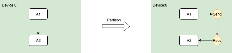
這個過程的關鍵是在插入Send和Recv節點之後,需要插入額外的Control Edge,程式碼如下。
// Fix up the control flow edge.
// NOTE(yuanbyu): 'real_recv' must be the real recv node.
if (src_graph == dst_graph) {
  // For same device send/recv, add a control edge from send to recv.
  // This prevents the asynchronous recv kernel from being scheduled
  // before the data is available.
  AddInput(real_recv, send->name(), Graph::kControlSlot);
}
跨Device根據DataFlow插入Send和Recv節點對
這是最容易理解的一種情況,Send節點需要插入到和src節點相同的Device上,Recv需要插入到和dst節點相同的Device上。並且為了減少不必要的通訊開銷,儘可能的重用Recv節點。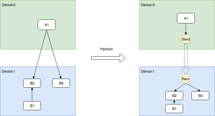 該過程的關鍵在於複用Recv節點,前面在獲取快取時已經闡述過,這裡不重複展示。
跨Device根據ControlFlow插入Send和Recv節點對
當存在跨Device的Control Flow依賴時,問題變得相對複雜。因為Control Edge只是用作控制,它並不傳輸真正的Tensor,但在跨Device的情況下,必須要向dst所在的Device傳送訊息,讓其知曉存在依賴控制。TensorFlow選擇傳送DummyConst的方式通知dst節點,具體而言,需要在src的Device上插入shape為0的DummyConst節點,然後將其作為Send的唯一輸入,並將src節點作為它的Control Dependncy。另一方面,在dst的Device上插入Recv節點之後,還需要插入一個identity節點負責讀取傳送來的DummyConst,然後將Indentity作為dst的Control Dependency。如此一來,這種跨Device的依賴關係就可以被完全等價的表示出來。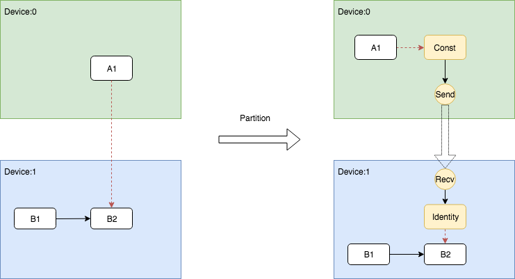 這個過程的關鍵在於src端的DummyConst插入和dst端的Identity插入,這兩部分的邏輯處理寫在了兩個地方。DummyConst和相關控制依賴的程式碼如下。
 1       NodeDefBuilder::NodeOut send_from;
 2       if (edge->IsControlEdge()) {
 3         // Insert a dummy const node that will generate a tiny
 4         // data element to be sent from send to recv.
 5         VLOG(1) << "Send/Recv control: " << src->assigned_device_name() << "["
 6                 << src->name() << "] -> " << dst->assigned_device_name() << "["
 7                 << dst->name() << "]";
 8         NodeDef* dummy = AddDummyConst(opts, src_graph, edge, &status);
 9         if (!status.ok()) return status;
10         // Set the start time for this dummy node.
11         if (opts.scheduling_for_recvs) {
12           AddNodeAttr("_start_time", send_start_time, dummy);
13         }
14         AddInput(dummy, src->name(), Graph::kControlSlot);
15         send_from.Reset(dummy->name(), 0, DT_FLOAT);
16       } else {
17         send_from.Reset(src->name(), edge->src_output(), EdgeType(edge));
18       }
Indentity即相關依賴的插入邏輯被寫在了AddRecv中,下面展示了這個片段。
 1   // Add the cast node (from cast_dtype to dtype) or an Identity node.
 2   if (dtype != cast_dtype) {
 3     const string cast_op = (host_memory) ? "_HostCast" : "Cast";
 4     NodeDefBuilder cast_builder(opts.new_name(src->name()), cast_op);
 5     cast_builder.Attr("DstT", dtype);
 6     cast_builder.Device(dst->assigned_device_name())
 7         .Input(recv->name(), 0, cast_dtype);
 8     NodeDef* cast = gdef->add_node();
 9     *status = cast_builder.Finalize(cast);
10     if (!status->ok()) return nullptr;
11     return cast;
12   } else if (edge->IsControlEdge()) {
13     // An Identity is only needed for control edges.
14     NodeDefBuilder id_builder(opts.new_name(src->name()), "Identity");
15     id_builder.Device(dst->assigned_device_name())
16         .Input(recv->name(), 0, cast_dtype);
17     NodeDef* id = gdef->add_node();
18     *status = id_builder.Finalize(id);
19     if (!status->ok()) return nullptr;
20     return id;
21   } else {
22     return recv;
23   }
關於使用bfloat16壓縮通訊
TensorFlow支援通過使用bfloat16減少通訊量,雖然bfloat16理論上是有損精度的,但是大量的實踐證明這個精度損失是基本感知不到的。bfloat16的通訊功能可以通過以下配置項開啟,只要在建立Session時傳入開啟該功能的config即可。
graph_options = tf.GraphOptions(enable_bfloat16_sendrecv=True)
session_config = tf.ConfigProto(gpu_options=gpu_options)
而TensorFlow在底層插入bfloat的轉換節點就是在Graph Partitioner的AddSend函式和AddRecv函式中插入的,但是這個轉換隻會在跨Device的Send和Recv前後插入,這也非常符合邏輯,因為處於同一個Device的Send和Recv本質上是本地的Memory Copy,其頻寬非常高,所以通訊並不是瓶頸,而插入兩個轉換節點只能帶來額外的轉換開銷。