
基於QT:溫度串列埠影象顯示
用Qt自己寫一個上位機,將串列埠發過來的溫度資訊,顯示出來,並且繪畫出溫度曲線
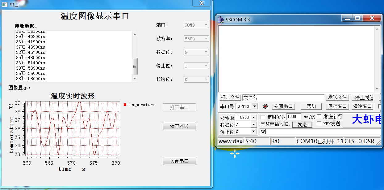
上圖:
採用QT繪畫曲線,首先當然是採用,qwt控制元件,而Qt沒有自帶的qwt控制元件,所以需要按住移植qwt控制元件方法具體步驟如下:
1. Download and install QT 5.0.1 (MinGw) to: “C:\Qt\Qt5.0.1”
2. Download and extract Qwt 6.1 RC3 to: “C:\qwt-6.1-rc3”
3. Add “C:\Qt\Qt5.0.1\5.0.1\mingw47_32\bin” to your systems path variable (qmake.exe is located here)
4. Add “C:\Qt\Qt5.0.1\Tools\MinGW\bin” to your systems path variable (mingw32-make.exe is located here)
5. Open a command line (cmd) and navigate to: “C:\qwt-6.1-rc3”
6. Type: “qmake” (This command won’t prompt any msg so don’t worry)
7. Type: “mingw32-make” (Compiles the whole project with examples; this will take a while so be patient)
8. Type: “mingw32-make install” (This installs qwt to the directory set in “C:\qwt-6.1-rc3\qwtconfig.pri”; the default location is “C:/Qwt-QWT_VERSION-rc3” -> “C:\Qwt-6.1.0-rc3\”)
9. Add “C:\Qwt-6.1.0-rc3\lib” to your systems path variable
10. Add a User variable named “QT_PLUGIN_PATH” with the following path “C:\Qwt-6.1.0-rc3\plugins”
11. Add a User variable named “QMAKEFEATURES” with the following path “C:\Qwt-6.1.0-rc3\features”
12. Start Qt Creator
13. Create a new project: File -> New File or Project … -> Applications -> Qt Gui Application -> Choose
14. Name it “Test”
15. Create the project in the following directory: “C:\workspace”
16. Open file “Test.pro”
17. Add “Config += qwt” at the bottom
18. Open the main.c of the project and delete all its content.
19. Paste the following in the main.c (This is the qwt example “simpleplot”):
既如下步驟,當然,中國網站上大多數都是採用直接新增一些LIB到.pro檔案中去,個人感覺這種方法不是很好,所以就翻牆看了看:
1.下載並安裝QT 5.0.1(MinGW的)到“C:\ Qt的\ Qt5.0.1”
2.下載並解壓縮QWT 6.1 RC3到:“C:\ QWT-6.1-RC3”
3.新增“C:\ Qt的\ Qt5.0.1 \ 5.0.1 \ mingw47_32 \ BIN”到你的系統路徑變數(qmake.exe就設在這裡)
4.新增“C:\ Qt的\ Qt5.0.1 \ TOOLS \ MinGW的\ BIN”到你的系統路徑變數(的mingw32-的make.exe就設在這裡)
5.開啟命令列(CMD)並導航到:“C:\ QWT-6.1-RC3”
6.鍵入:“qmake”(該命令將不會提示任何MSG所以不用擔心)
7.鍵入“mingw32-make”(編譯舉例整個專案,這將需要一段時間,所以要耐心等待)
8.鍵入:“mingw32-make install”(這將安裝QWT在“C:\ QWT-6.1-RC3 \ qwtconfig.pri”設定的目錄;預設位置是“C:/ QWT - $$ QWT_VERSION-RC3” - >“C:\ QWT-6.1.0-RC3 \”)
9.新增“C:\ QWT-6.1.0-RC3 \ LIB”你的系統路徑變數
10.新增一個名為“QT_PLUGIN_PATH”使用者變數具有以下路徑:“C:\Qwt-6.1.0-rc3\plugins”
11.新增一個名為“QMAKEFEATURES”使用者變數具有以下路徑:“C:\Qwt-6.1.0-rc3\features”
12.啟動Qt Creator的
13.建立一個新的專案:檔案 - >新建檔案或專案… - >應用程式 - > Qt的GUI應用程式 - >選擇
14.將它命名為“測試”
15.在以下目錄中建立專案:“C:\workspace”
16.開啟檔案“Test.pro”
17.新增“CONFIG += qwt”在底部
18.開啟專案的main.c中並刪除其所有內容。
19.貼上在main.c中以下(這是QWT榜樣“simpleplot”):
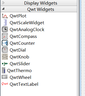
這樣就能夠在ui介面編輯中找到QwtWidgets包含的控制元件類了。當然開啟ui是要選擇以QT designed 才能夠找到這些控制元件,如下圖:

接著就是設計好ui介面了,如上圖所示的介面,
新增原始碼:
.pro檔案
QT += core gui
CONFIG += qwt
QT +=serialport
greaterThan(QT_MAJOR_VERSION, 4): QT += widgets
TARGET = temperature
TEMPLATE = app
SOURCES += main.cpp\
mainwindow.cpp
HEADERS .h檔案
#ifndef MAINWINDOW_H
#define MAINWINDOW_H
#include <QMainWindow>
#include <QMessageBox>
#include <QTimer>
#include <QDebug>
#include <QtSerialPort/QSerialPort>
#include <QtSerialPort/QSerialPortInfo>
#include <qwt_plot_curve.h> .cpp檔案
#include "mainwindow.h"
#include "ui_mainwindow.h"

QwtPlotCurve *curve = new QwtPlotCurve("temperature");
//定義一個QWtPlotCurve類的物件,curve  用來繪畫曲線
//右邊圖例初始化,名字為“temperature”

//X軸
double time[20] = {};
//Y軸
double val[20] ={};
    int time_count;

MainWindow::MainWindow(QWidget *parent) :
    QMainWindow(parent),
    ui(new Ui::MainWindow)
{
    ui->setupUi(this);
//    ui->temperplot->resize(640,400);
    setWindowFlags(Qt::WindowCloseButtonHint);//只顯示一個關閉按鈕
    //固定介面大小不可改變
    setMaximumSize(this->width(),this->height());
    setMinimumSize(this->width(),this->height());
    //設定影象顯示標題
    ui->temperplot->setTitle("溫度實時波形");
    //設定座標軸名稱
    ui->temperplot->setAxisTitle(QwtPlot::xBottom,"time   s");
    ui->temperplot->setAxisTitle(QwtPlot::yLeft,"temperature  ℃");

//    //設定座標軸的範圍
//    ui->temperplot->setAxisScale(QwtPlot::yLeft,0,50);
//    ui->temperplot->setAxisScale(QwtPlot::xBottom,0,5);
    //改變繪圖區域的背景,canvas 表示畫布
    ui->temperplot->canvas()->setPalette(QPalette(QColor(Qt::white)));
//    //使用滾輪放大縮小
//    (void) new QwtPlotMagnifier(ui->temperplot->canvas());
//    (void) new QwtPlotPanner(ui->temperplot->canvas());

    (new QwtPlotPanner(ui->temperplot->canvas()))->setMouseButton(Qt::RightButton);
    (new QwtPlotMagnifier(ui->temperplot->canvas()))->setAxisEnabled(QwtPlot::yLeft,false);
       //y軸在放大的時候,座標不變化

    QwtPlotZoomer* zoomer = new QwtPlotZoomer(ui->temperplot->canvas());
    zoomer->setRubberBandPen(QColor(Qt::black));
    zoomer->setTrackerPen(QColor(Qt::black));
    zoomer->setMousePattern(QwtEventPattern::MouseSelect2,Qt::RightButton,Qt::ControlModifier);
    zoomer->setMousePattern(QwtEventPattern::MouseSelect3,Qt::RightButton);
    //實現滑鼠左鍵選擇區域放大:(右鍵還原)功能。

    //定義一個選擇器,(十字架),以xBottom 和yLeft為座標顯示
    QwtPlotPicker *picker;
    picker = new QwtPlotPicker(QwtPlot::xBottom,QwtPlot::yLeft,QwtPlotPicker::CrossRubberBand,QwtPicker::AlwaysOn,ui->temperplot->canvas());
    picker->setStateMachine(new QwtPickerDragPointMachine());//拖拽點起作用
    picker->setRubberBandPen(QPen(QColor(Qt::white)));//拖拽點顏色
    picker->setTrackerPen(QColor(Qt::blue));//跟蹤器 顯示對應座標的顏色

    QwtLegend *legend = new QwtLegend;//legend(圖例)
    legend->setDefaultItemMode(QwtLegendData::Checkable);//圖例可選擇
    ui->temperplot->insertLegend(legend,QwtPlot::RightLegend);//圖例插入到plot繪畫中。

    QwtPlotGrid *grid = new QwtPlotGrid;//grid 格子,網格
    grid->enableXMin(true);
    grid->setMajorPen(QPen(Qt::red, 0, Qt::DotLine));//大格子
    grid->setMinorPen(QPen(Qt::red, 0 , Qt::DotLine));//大格子裡的小格子
    grid->attach(ui->temperplot);//載入到plot中

    setAutoFillBackground(true);//自動填充背景顏色
    curve->setPen(QPen(Qt::red));
    curve->setSamples(time,val,20);//載入資料,也可以使用setData
//    curve->setSamples(xs,ys);
    curve->setCurveAttribute(QwtPlotCurve::Fitted,true);//是曲線更圓滑
    curve->attach(ui->temperplot);//載入到plot繪畫上

    //連線槽,處理對應事件
    connect(legend,SIGNAL(checked(const QVariant &,bool,int)),this,SLOT(legendChecked(const QVariant &,bool)));

    /*串列埠部分*/
    /*查詢可用串列埠,呼叫foreach 串列埠資訊儲存在info 中*/
    foreach (const QSerialPortInfo &info,QSerialPortInfo::availablePorts())
    {
        qDebug() <<"Name   :" <<info.portName();
        qDebug() <<"Description" <<info.description();
        qDebug() <<"Manufacturer"<<info.manufacturer();

        QSerialPort serial;
        serial.setPort(info);//設定串列埠埠
        if(serial.open(QIODevice::ReadWrite))//可讀可寫方式開啟串列埠
        {
            ui->portBox->addItem(serial.portName());//將檢測到的串列埠資訊放到Box中顯示
            serial.close();
        }
    }
    ui->closeButton->setEnabled(false);//關閉按鈕不可用
    ui->clearButtom->setEnabled(false);//清空資料按鈕不可以
    qDebug() <<tr("介面設定成功");
    connect(ui->openButton,SIGNAL(clicked()),this,SLOT(OpenButtonClicked()));
    connect(ui->closeButton,SIGNAL(clicked()),this,SLOT(closeButtonClicked()));
    connect(ui->clearButtom,SIGNAL(clicked()),this,SLOT(clearButtonClicked()));
}

MainWindow::~MainWindow()
{
    delete ui;
}
void MainWindow::legendChecked(const QVariant &itemInfo,bool on)
{
    //獲得曲線
    QwtPlotItem *plotItem = ui->temperplot->infoToItem(itemInfo);
    if(plotItem)
    {
        plotItem->setVisible(on);
    }
    ui->temperplot->replot();//重新載入曲線
}

//開啟串列埠槽函式
void MainWindow::OpenButtonClicked()
{

    if(ui->portBox->currentText() == NULL)
    {
        QMessageBox::information(this,"Error Message","Open port Error");
    }
    else
    {
        ui->openButton->setEnabled(false);
        ui->clearButtom->setEnabled(true);
        ui->closeButton->setEnabled(true);//使能關閉串列埠
        //設定各個組合框不可用
        ui->portBox->setEnabled(false);
        ui->dataBox->setEnabled(false);
        ui->checkBox->setEnabled(false);
        ui->stopBox->setEnabled(false);
        ui->baudrateBox->setEnabled(false);

       serial = new QSerialPort;

       //設定埠名com x; 這兩句的順序不能夠變,否則會出錯。
       serial->setPortName(ui->portBox->currentText());
       //開啟串列埠
       serial->open(QIODevice::ReadWrite);
       //設定波特率
//       serial->setBaudRate(ui->baudrateBox->currentText().toInt());
       if(ui->baudrateBox->currentText()==tr("9600")) //根據組合框內容對串列埠進行設定
           serial->setBaudRate(QSerialPort::Baud9600);
           else if(ui->baudrateBox->currentText()==tr("115200"))
           serial->setBaudRate(QSerialPort::Baud115200);
       //設定資料位
       switch(ui->dataBox->currentIndex())
       {
            case 8:serial->setDataBits(QSerialPort::Data8);
                    break;
            case 7:serial->setDataBits(QSerialPort::Data7);
                    break;
            default :
                    break;
       }
       //設定校驗位
       switch (ui->checkBox->currentIndex())
       {
            case 0:serial->setParity(QSerialPort::NoParity);
                break;
            default:
                break;
       }
       //設定停止位
       switch (ui->stopBox->currentIndex())
       {
            case 1:serial->setStopBits(QSerialPort::OneStop);
                break;
            default:
            break;
       }
       //設定流控制
       serial->setFlowControl(QSerialPort::NoFlowControl);
        //連線槽函式,當串列埠有資料到來時,回撥函式。
        connect(serial,SIGNAL(readyRead()),this,SLOT(Read_Data()));

        QTimer *timer_clock = new QTimer(this);
        connect(timer_clock,SIGNAL(timeout()),this,SLOT(timeoutslot()));
        timer_clock->start(100);//200ms

    }
}

void MainWindow::closeButtonClicked()
{
    ui->openButton->setEnabled(true);
    ui->closeButton->setEnabled(false);
    ui->clearButtom->setEnabled(false);

    //設定各個組合框可以
    ui->portBox->setEnabled(true);
    ui->dataBox->setEnabled(true);
    ui->checkBox->setEnabled(true);
    ui->stopBox->setEnabled(true);
    ui->baudrateBox->setEnabled(true);

    serial->clear();
    serial->close();
    serial->deleteLater();

}

void MainWindow::Read_Data()//進去這個函式是,只要串列埠中有資料,就會進入這個函式。
{
    QByteArray buf;//QByteArray 類是定義一個位元組陣列(char *),
    buf = serial->readAll();//讀取串列埠所有的資料給變數buf
    if(buf != NULL)
    {
        QString str = ui->receiveEdit->toPlainText();//獲取TextEdit的內容

        for (int i = 0; i < 19; i++)
        {
            val[i] = val[i+1];
        }
        //最後一位為新資料
        val[19] =buf.toDouble();
        curve->setSamples(time,  val, 20);//重新載入資料
//        ys.append(buf.toDouble());
//        curve->setSamples(xs,ys);
        ui->temperplot->replot(); //QwtPlot重繪,重要,沒有這句不起作用

        str = tr(buf);//將接收區之前的資料+串列埠緩衝區的資料
        QString str1,str2;
        str1 = str+tr("℃ ");
        str2 = QString::number(time_count*100);//int --> Qstring
        str1 += str2+tr("ms");
     //   ui->receiveEdit->clear();
        ui->receiveEdit->append(str1);//把文字str新增到文字編輯的結尾
    }
    buf.clear();
}


void MainWindow::clearButtonClicked()
{
    ui->receiveEdit->clear();
    memset(time,0,20);
    memset(val,0,20);
    time_count = 0;
}

//定時100ms一到,回撥這個函式
void MainWindow::timeoutslot()
{
    time_count++;
    for(int i = 0;i < 19;i++)
    {
        time[i]=time[i+1];
    }
    time[19] = time_count;
}
版權所有,轉發請註明出處:
http://blog.csdn.net/qq_33559992/article/details/52238116