Simple UART communication protocol in XOD


Simple UART communication protocol in XOD
Greetings, XODers!
This article is the quick guide to working with the gabbapeople/simple-byte-protocol library in XOD.
You can use this library to create own simple byte communication protocols. Using own protocol you can transfer byte packets of data from one device to another without fear of breakage or loss. You can also use this library to create your byte commands to control your robot or any other device.
Concept
The point is simple. Data is transmitted through a UART interface as a packet of bytes. The sending side configures the byte packet and packs your data. The other side receives the packet checks it and parses it if the packet arrived undamaged.


Each new Packet starts with a “header” byte. This byte is used to determine the beginning of the packet and reports that bytes which contain data follow it.
The specified number of bytes of data is followed by the “checksum” byte. The sending part counts the “checksum” for the data and sends the package. The receiving part reads the package and considers its checksum. If the checksum is equal to the one specified by the sending side, the packet arrived undamaged and can it can be used.
Nodes overview
Let’s look at all the library nodes.
Packet node
This node сreates a packet type of a specific size. It is used on both the sending and receiving side.


SIZEpin — specifies the size for the package. Note, that this value determines the size of the whole package, not just the part that contains your data. For example, to send a packet with 3 values, you need a 5-sized packet, because you also need a 2-byte space for a “header” and “checksum”.PCKTpin — outputs thepacketcustom type value for a created packet.
Add-head node
The add-head is used on the sending side. It should follow a packet node.
This node takes the packet type value and adds a “header” byte to the beginning of the packet. Then, the add-head node passes the packet further.


HEAD pin specifies the “header” byte for the package. Here, put a hexadecimal value, for example 20h. Also, I can use different HEAD values to define a particular command of your robot, for example 30h “header” for the “run forward” command and 31h for “run backward”.
Add-byte-to-packet node
The add-byte-to-packet is used on the sending side.
This node takes the packet type value and fulfills it with values. Values are specified in a byte form.


Through the B pin a data value is placed into a packet. The sequence number of a B pin determines the sequence number for value at this pin in a packet.
Add-checksum node
The add-checksum is used on the sending side. It should follow an add-byte-to-packet node.
This node takes a packet filled with data and calculates it’s “checksum”. Then, the add-checksum adds the “checksum” byte to the end of a packet and passes it further.


CSB pin specifies a special byte value. Here, put a hexadecimal value, for example, FFh. A “checksum” byte of your packet is calculated with this unique CSB byte, thus eliminating the possibility of reading a random “checksum” byte on a receiving side.
Send-packet node
The send-packet is used on the sending side.
This node takes a formed packet and sends it via UART.


UART— the pin of the customUARTtype for an interface you use.PCKT— the pin for thepacketto be sent.SEND— the pin that triggers a newpacketsent.DONE— the pin fires on a successfulpacketsent.ERR— the pin fires on a failedpacketsent.
Read-packet node
The read-packet is used on the receiving side. It should follow a packet node.
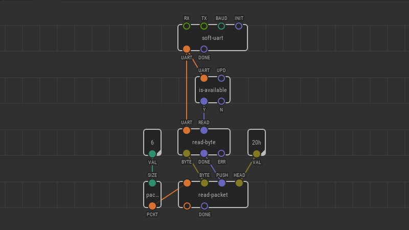
This node takes the packet type value and continuously compares the specified “header” byte with the byte received through a UART interface. If a “header” byte is found, read-packet puts the received bytes into a packet of the specified size. Then, the read-packet node passes the packet further.
To read bytes directly from UART, use the read-byte node from the xod/uart library.


BYTE— the pin for an incoming byte.PUSH— triggers a new “header” match.HEAD— a “header” hexadecimal value of a byte type, for example20h. Note, that the “header“ byte values should be equal on the receiving and sending sides.DONE— fires if a “header” is found.
Check-packet node
The check-packet is used on the receiving side. It should follow a read-packet node.
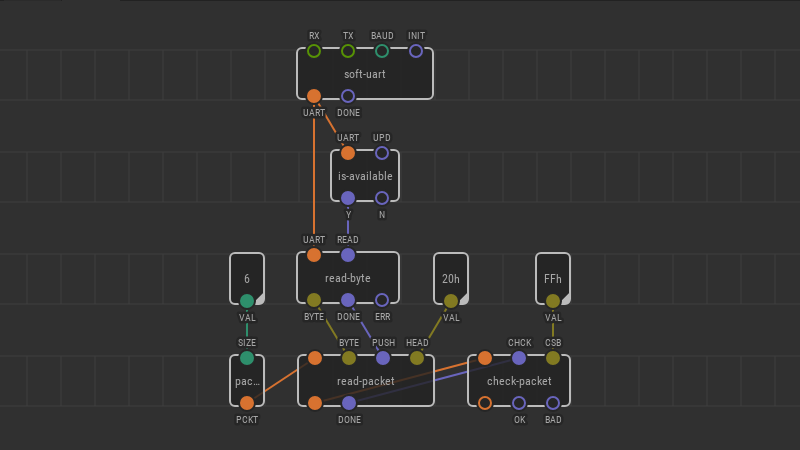
This node takes a packet from the read-packet node and calculates it’s “checksum”. If the calculated “checksum” matches the one mentioned in a packet, then a packet arrived undamaged.


CHCK— triggers a newpacketcheck.CSB— A “checksum” byte of your packet is calculated with this uniqueCSBbyte. Note, that the “checksum“ byte values should be equal on the receiving and sending sides.OK— fires if apacketarrived undamaged.BAD— fires on a brokenpacket.
Get-byte-from-packet node
The get-byte-from-packet is used on the receiving side. It should follow a check-packet node.
This node takes an unbroken packet from the check-packet node and pulls a byte value from it depending on the sequence number of a byte.


IDX— sequence number of the byte to pull from apacket.GET— triggers a new pull of a byte.
Example
The following is an example of transmitting 4 values from potentiometers using this simple byte protocol.
Sending side
Create a new patch for a sending side.
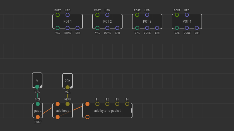
Set up a new packet using the packet node. To send 4 values, you need to set the SIZE to 6. (4 data bytes + header byte + checksum byte).


Set a “header” byte for a packet. Put the add-head node and link it with the packet. Put a byte value to the HEAD pin. Let it be 20h.


Then, add the add-byte-to-packet node to fill the packet with data. Extend the add-byte-to-packet variadic node up to 4 bytes.


Add four pot nodes.
The value from the first potentiometer will be transmitted in the first data byte of the packet.
The value from the second potentiometer will be transmitted in the second data byte of the packet. Etc.

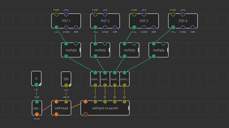
A potentiometer node outputs a number type value in the [0,1] range. The add-byte-to-packet node inputs a byte type value in the range [0,255]. Therefore, you need to convert pot values.
To convert a number type value to the byte type use the number-to-u8 node from the xod/bits library. To change ranges, you can multiply pot values by 100. Alternatively, you can use the map-clip node.

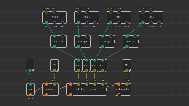
Calculate the checksum. Add the add-checksum node onto the patch and link it with the add-byte-to-packet node. Set the CSB byte value. Let it be FFh.

Set up a UART interface to transfer a packet. Add the send-packet node and link it with the add-checksum node. You can adjust the frequency of sending new packets using the SEND pin.

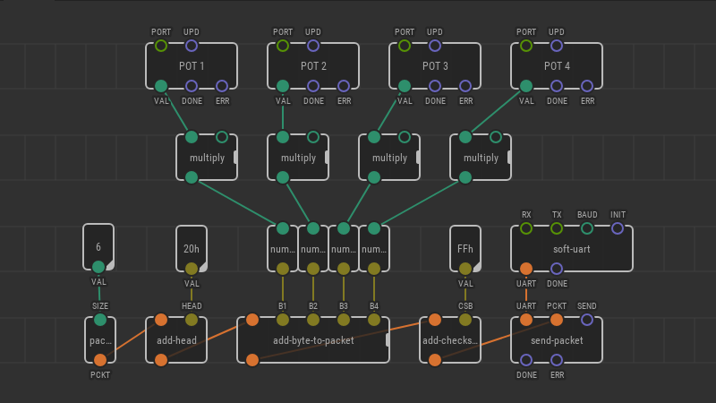
The sender side patch is complete.
Receiving side
Create a new patch for a receiving side.
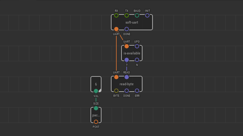
Again, set up a new packet using the packet node. To receive 4 values, you need to set the SIZE to 6. (4 data bytes + header byte + checksum byte).


Set up a UART interface. read-byte from the UART if it is available. Set the UPD pin value to Continuously.

Now, add the read-packet node onto the patch and link it with the packet node. Also, link its BYTE and PUSH pins with the read-byte node. Set up a HEAD byte value to find a packet through the stream. HEAD value should be the same as at the sending side.

Check a received packet. Put the check-packet node and link it with the read-packet. The CSB value should be the same as at the sending side.

If a packet is OK, you can pull values from it using the get-byte-from-packet node.
Add four get-byte-from-packet nodes for four received values and link them with the check-packet node. Set the IDX pin values depending on the byte order. For the first pot, the IDX is 1. For the second pot, the IDX is 2. Etc.
To convert a value from the byte type to the number use the u8-to-number node from the xod/bits library.

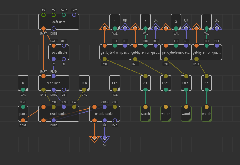
The sender side patch is complete. You can upload both patches to your devices and check their work.
Try this library to create simple protocols in your projects. Put your feedback on the XOD forum.
