基於FPGA的CORDIC演算法實現——Verilog版
目前,學習與開發FPGA的程式設計師們大多使用的是Verilog HDL語言(以下簡稱為Verilog),關於Verilog的諸多優點一休哥就不多介紹了,在此,我們將重點放在Verilog的運算操作上。
我們都知道,在Verilog中,運算一般分為邏輯運算(與或非等)與算術運算(加減乘除等)。而在一開始學習Verilog時,老司機一定會提醒我們,“切記,千萬別用‘/’除、‘%’取模(有的也叫取餘)和‘**’冪。”這話說的不無道理,因為這三個運算是不可綜合的。但,需清楚理解的是,不可綜合的具體意思為不能綜合為簡單的模組,當我們在程式中呼叫了這些運算時,‘/’除和‘%’取模在Quartus軟體中是可以綜合的,因此可以正常呼叫執行,但是會消耗一些邏輯資源,而且會產生延時,即這兩個運算的處理時間會很長,可能會大於時序控制時鐘的單週期時間。此時呢,我們會建議你呼叫IP核來實現運算操作,雖然這樣也會消耗許多邏輯資源,但產生的延時相對較小滿足了你基本的需求。
問題好像迎刃而解了,可是仔細一想,除了這些運算,我們還剩下什麼?對呀,三角函式,反三角函式,對數函式,指數函式呢,這些函式我們在高中就學習了的呀,難道在FPGA中就沒有用武之地嗎?有人會說,查詢表唄,首先將某個運算的所有可能的輸入與輸出對一一羅列出來,然後放進Rom中,然後根據輸入查表得到輸出。這個方法雖然有效的避免了延時問題,卻是一個十分消耗資源的方法,不適合資源緊張的設計。那麼,就真的沒有辦法了嗎?
答案就是咱們今天的標題了,CORDIC,而且CORDIC是一個比較全能的演算法,通過這一原理,我們可以實現三角函式,反三角函式,對數函式,指數函式等多種運算。接下來,一休哥就帶領大家來學習CORDIC的原理吧。(題外話:請相信一休哥,本文不會讓你感到太多痛苦~)
本文將分三個小部分來展開介紹:
1、CORDIC的基本原理介紹
2、CORDIC的具體操作流程介紹
3、CORDIC的旋轉模式——Verilog模擬
本文涉及到的全部資料連結:
連結:
一、CORDIC的基本原理介紹
CORDIC演算法是一個“化繁為簡”的演算法,將許多複雜的運算轉化為一種“僅需要移位和加法”的迭代操作。CORDIC演算法有旋轉和向量兩個模式,分別可以在圓座標系、線性座標系和雙曲線座標系使用,從而可以演算出8種運算,而結合這8種運算也可以衍生出其他許多運算。下表展示了8種運算在CORDIC演算法中實現的條件。

首先,我們先從旋轉模式下的圓座標系講起,這也是CORDIC方法最初的用途。
1、CORDIC的幾何原理介紹
假設在xy座標系中有一個點P1(x1,y1),將P1點繞原點旋轉θ角後得到點P2(x2,y2)。

於是可以得到P1和P2的關係。
x2 = x1cosθ – y1sinθ = cosθ(x1 – y1tanθ)
y2 = y1cosθ + x1sinθ = cosθ(y1 +x1tanθ)
以上就是CORDIC的幾何原理部分,而我們該如何深入理解這個幾何原理的真正含義呢?
從原理中,我們可以知道,當已知一個點P1的座標,並已知該點P1旋轉的角度θ,則可以根據上述公式求得目標點P2的座標。然後,麻煩來了,我們需要用FPGA去執行上述運算操作,而FPGA的Verilog語言根本不支援三角函式運算。因此,我們需要對上述式子進行簡化操作,將複雜的運算操作轉換為一種單一的“迭代位移”演算法。那麼,接下來我們介紹優化演算法部分。
2、CORDIC的優化演算法介紹
我們先介紹演算法的優化原理:將旋轉角θ細化成若干分固定大小的角度θi,並且規定θi滿足tanθi = 2-i,因此∑θi的值在[-99.7°,99.7°]範圍內,如果旋轉角θ超出此範圍,則運用簡單的三角運算操作即可(加減π)。
然後我們需要修改幾何原理部分的假設,假設在xy座標系中有一個點P0(x0,y0),將P0點繞原點旋轉θ角後得到點Pn(xn,yn)。
於是可以得到P0和Pn的關係。
xn = x0cosθ – y0sinθ = cosθ(x0 – y0tanθ)
yn = y0cosθ + x0sinθ = cosθ(y0 + x0tanθ)
然後,我們將旋轉角θ細化成θi,由於每次的旋轉角度θi是固定不變的(因為滿足tanθi = 2-i),如果一直朝著一個方向旋轉則∑θi一定會超過θ(如果θ在[-99.7°,99.7°]範圍內)。因此我們需要對θi設定一個方向值di。如果旋轉角已經大於θ,則di為-1,表示下次旋轉為順時針,即向θ靠近;如果旋轉角已經小於θ,則di為1,表示下次旋轉為逆時針,即也向θ靠近。然後我們可以得到每次旋轉的角度值diθi,設角度剩餘值為zi+1,則有zi+1 = zi - diθi,其中z0為θ。如此隨著i的增大,角度剩餘值zi+1將會趨近於0,此時運算結束。(注:可以發現,di與zi的符號位相同)
第一次旋轉θ0,d0為旋轉方向:
x1 = cosθ0(x0 – d0y0tanθ0)
y1 = cosθ0(y0 + d0x0tanθ0)
第二次旋轉θ1,d1為旋轉方向:
x2 = cosθ1(x1 – d1y1tanθ1) = cosθ1cosθ0(x0 – d0y0tanθ0 – d1y0tanθ1 – d1d0 x0tanθ1 tanθ0)
y2 = cosθ1(y1 + d1x1tanθ1) = cosθ1cosθ0(y0 + d0x0tanθ0 + d1x0tanθ1 – d1d0y0tanθ1 tanθ0)
大家可能已經發現了,在我們旋轉的過程中,式子裡一直會有tanθi和cosθi,而每次都可以提取出cosθi。雖然我們的FPGA無法計算tanθi,但我們知道tanθi = 2-i,因此可以執行和tanθi效果相同的移位操作2-i來取代tanθi。而對於cosθi,我們可以事先全部提取出來,然後等待迭代結束之後(角度剩餘值zi+1趨近於0,一般當系統設定最大迭代次數為16時zi+1已經很小了),然後計算出∏cosθi的值即可。
總結一下:
迭代公式有三:
xi+1 = xi – d iy i2-i,提取了cosθi,2-i等效替換了tanθi之後
yi+1 = yi + d ix i2-i,提取了cosθi,2-i等效替換了tanθi之後
zi+1 = zi - diθi
其中i從0開始迭代,假設當i = n-1時,zn趨近於0,迭代結束。然後對結果乘上∏cosθi(i從0至n-1),於是得到點Pn(xn∏cosθi,yn∏cosθi),此時的點Pn就近似等於之前假設中的點Pn(xn,yn)了,所以此時的點Pn同樣滿足之前假設得到的公式:
xn∏cosθi = x0cosθ – y0sinθ
yn∏cosθi = y0cosθ + x0sinθ
由於i從0至n-1,所以上式可以轉化成下式:
xn = 1/∏cosθi(x0cosθ – y0sinθ),(其中i從0至n-1)
yn = 1/∏cosθi(y0cosθ + x0sinθ),(其中i從0至n-1)
注意:上式中的xn,yn是經過迭代後的結果,而不是之前假設中的點Pn(xn,yn)。瞭解這點是十分重要的。
根據高中學的三角函式關係,可以知道cosθi = 1/[(1+tan2θi)^0.5] = 1/[(1+2-2i)^0.5],而1/[(1+2-2i)^0.5]的極值為1,因此我們可以得出一個結論:當i的次數很大時,∏cosθi的值趨於一個常數。
關於如何計算∏cosθi的程式碼如下所示:
close all;
clear;
clc;
% 初始化
die = 16;%迭代次數
jiao = zeros(die,1);%每次旋轉的角度
cos_value = zeros(die,1);%每次旋轉的角度的餘弦值
K = zeros(die,1);%餘弦值的N元乘積
K_1 = zeros(die,1);%餘弦值的N元乘積的倒數
for i = 1 : die
    a = 2^(-(i-1));
    jiao(i) = atan(a);
    cos_value(i) = cos(jiao(i));
    if( i == 1)
        K(i) = cos_value(i);
        K_1(i) = 1/K(i);
    else
        K(i) = K(i-1)*cos_value(i);
        K_1(i) = 1/K(i);
    end
end
jiao = vpa(rad2deg(jiao)*256,10)
cos_value = vpa(cos_value,10)
K = vpa(K,10)
K_1 = vpa(K_1,10)
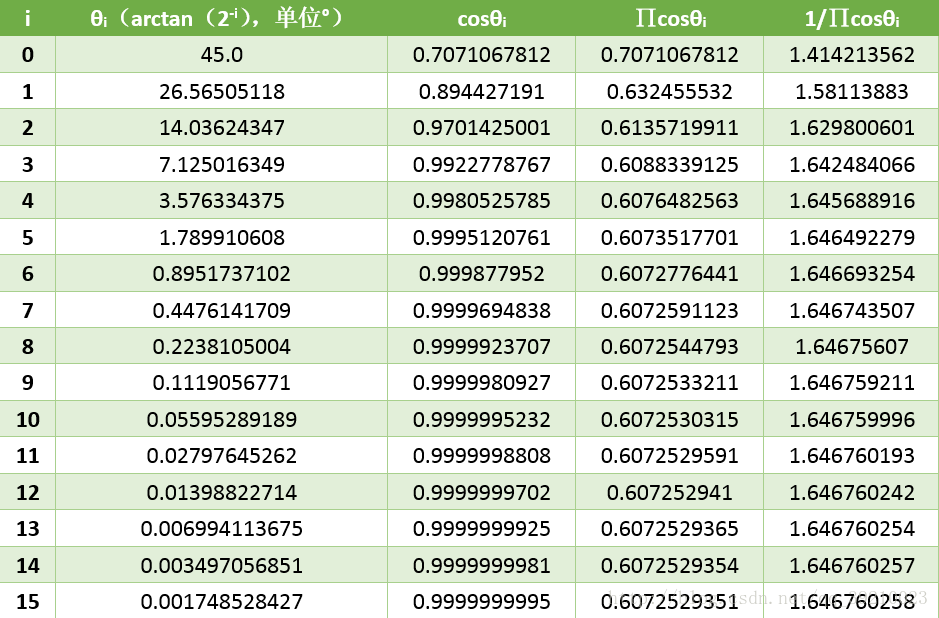
從上表也可以看出,當迭代次數為16,i=15時,cosθi的值已經非常趨近於1了,∏cosθi的值則約等於0.607253,1/∏cosθi為1.64676。所以當迭代次數等於16時,通過迭代得到的點Pn座標已經非常接近之前假設中的點Pn。所以,當迭代次數等於16時,這個式子是成立的。
xn = 1/∏cosθi(x0cosθ – y0sinθ),(其中i從0至n-1)
yn = 1/∏cosθi(y0cosθ + x0sinθ),(其中i從0至n-1)
此時,已知條件有三個x0、y0和θ。通過16次迭代,我們可以得到xn和yn。而式中的∏cosθi是個隨i變化的值,我們可以預先將其值存入系統中。
然後,我們人為設定x0 = ∏cosθi,y0 = 0,則根據等式,xn = cosθ,yn = sinθ。其中1/∏cosθi的值我們也同樣預先存入系統中。如此,我們就實現了正弦和餘弦操作了。
二、CORDIC的具體操作流程介紹
1、CORDIC的旋轉模式
由於演算法較複雜,一休哥再總結一些具體的操作流程。
1、 設定迭代次數為16,則x0 = 0.607253,y0 = 0,並輸入待計算的角度θ,θ在[-99.7°,99.7°]範圍內。
2、 根據三個迭代公式進行迭代,i從0至15:
xi+1 = xi – d iy i2-i
yi+1 = yi + d ix i2-i
zi+1 = zi - diθi
注:z0 = θ,di與zi同符號。
3、 經過16次迭代計算後,得到的x16 和y16分別為cosθ和sinθ。
至此,關於CORDIC的三角函式cosθ和sinθ的計算原理講解結束。
關於CORDIC演算法計算三角函式cosθ和sinθ的MATLAB程式碼如下所示:
close all;
clear;
clc;
% 初始化
die = 16;%迭代次數
x = zeros(die+1,1);
y = zeros(die+1,1);
z = zeros(die+1,1);
x(1) = 0.607253;%初始設定
z(1) = pi/4;%待求角度θ
%迭代操作
for i = 1:die
    if z(i) >= 0
        d = 1;
    else
        d = -1;
    end
    x(i+1) = x(i) - d*y(i)*(2^(-(i-1)));
    y(i+1) = y(i) + d*x(i)*(2^(-(i-1)));
    z(i+1) = z(i) - d*atan(2^(-(i-1)));
end
cosa = vpa(x(17),10)
sina = vpa(y(17),10)
c = vpa(z(17),10)
2、CORDIC的向量模式
講完了旋轉模式後,我們接著講講向量模式下的圓座標系。
在這裡,我們需從頭來過了,假設在xy座標系中有一個點P0(x0,y0),將P0點繞原點旋轉θ角後得到點Pn(xn,0),θ在[-99.7°,99.7°]範圍內。
於是可以得到P0和Pn的關係:
xn = x0cosθ – y0sinθ = cosθ(x0 – y0tanθ)
yn = y0cosθ + x0sinθ = cosθ(y0 + x0tanθ) = 0
如何得到Pn(xn,yn)一直是我們的目標。而此時,我們還是列出那幾個等式:
根據三個迭代公式進行迭代,i從0至15:
xi+1 = xi – d iy i2-i
yi+1 = yi + d ix i2-i
zi+1 = zi - diθi
不過此時我們嘗試改變初始條件:
設定迭代次數為16,則x0 = x,y0 = y,z0 = 0,di與yi的符號相反。表示,經過n次旋轉,使Pn靠近x軸。
因此,當迭代結束之後,Pn將近似接近x軸,此時yn = 0,可知旋轉了θ,即zn = θ = arctan(y/x)。
而
xn = 1/∏cosθi(x0cosθ – y0sinθ),(其中i從0至n-1)
yn = 1/∏cosθi(y0cosθ + x0sinθ),(其中i從0至n-1)
因此,可得ycosθ + xsinθ = 0,
xn = 1/∏cosθi(xcosθ – ysinθ) = 1/∏cosθi{ [ (xcosθ – ysinθ)^2]^(1/2)}
= 1/∏cosθi{ [ x2cos2θ + y2sin2θ – 2xysinθcosθ]^(1/2)}
= 1/∏cosθi{ [ x2cos2θ + y2sin2θ + y2 cos2θ + x2sin2θ]^(1/2)}
= 1/∏cosθi{ [ x2 + y2]^(1/2)}
由上可以知道,我們通過迭代,就算出了反正切函式zn = θ = arctan(y/x),以及向量OP0(x,y)的長度 d = xn * ∏cosθi。
關於反正切函式,一休哥要多囉嗦幾句了,由於θ在[-99.7°,99.7°]範圍內,所以我們輸入向量OP0(x,y)時,需要保證其在第一、四象限。
關於CORDIC演算法計算反三角函式arctanθ的MATLAB程式碼如下所示:
close all;
clear;
clc;
% 初始化
die = 16;%迭代次數
x = zeros(die+1,1);
y = zeros(die+1,1);
z = zeros(die+1,1);
x(1) = 100;%初始設定
y(1) = 200;%初始設定
k = 0.607253;%初始設定
%迭代操作
for i = 1:die
    if y(i) >= 0
        d = -1;
    else
        d = 1;
    end
    x(i+1) = x(i) - d*y(i)*(2^(-(i-1)));
    y(i+1) = y(i) + d*x(i)*(2^(-(i-1)));
    z(i+1) = z(i) - d*atan(2^(-(i-1)));
end
d = vpa(x(17)*k,10)
a = vpa(y(17),10)
c = vpa(rad2deg(z(17)),10)
三、CORDIC的旋轉模式——Verilog模擬
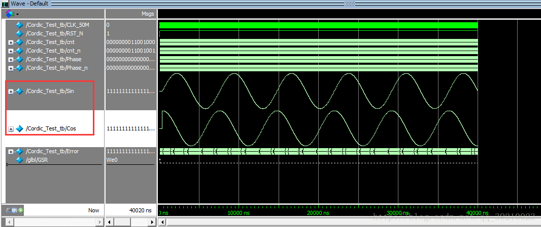
一休哥在編寫CORDIC演算法時,採用了16級流水線,模擬效果十分明顯。以下是頂層檔案的程式碼。
為了避免浮點運算,為了滿足精度要求,一休哥對每個變數都放大了2^16倍,並且引入了有符號型reg和算術右移。
關於Verilog程式碼的編寫,一休哥已經不想多說了,因為程式碼是完全符合我之前所講的CORDIC的原理與MATLAB模擬程式碼。相信大家在看完本文的前兩個部分之後,對Verilog的理解應該不是難事兒。
module Cordic_Test
(
    CLK_50M,RST_N,
    Phase,
    Sin,Cos,Error
);

input                       CLK_50M;
input                       RST_N;
input       [31:0]          Phase;
output      [31:0]          Sin;
output      [31:0]          Cos;
output      [31:0]          Error;

`define rot0  32'd2949120       //45度*2^16
`define rot1  32'd1740992       //26.5651度*2^16
`define rot2  32'd919872        //14.0362度*2^16
`define rot3  32'd466944        //7.1250度*2^16
`define rot4  32'd234368        //3.5763度*2^16
`define rot5  32'd117312        //1.7899度*2^16
`define rot6  32'd58688         //0.8952度*2^16
`define rot7  32'd29312         //0.4476度*2^16
`define rot8  32'd14656         //0.2238度*2^16
`define rot9  32'd7360          //0.1119度*2^16
`define rot10 32'd3648          //0.0560度*2^16
`define rot11 32'd1856          //0.0280度*2^16
`define rot12 32'd896           //0.0140度*2^16
`define rot13 32'd448           //0.0070度*2^16
`define rot14 32'd256           //0.0035度*2^16
`define rot15 32'd128           //0.0018度*2^16

parameter Pipeline = 16;
parameter K = 32'h09b74;    //K=0.607253*2^16,32'h09b74,

reg signed  [31:0]      Sin;
reg signed  [31:0]      Cos;
reg signed  [31:0]      Error;
reg signed  [31:0]      x0=0,y0=0,z0=0;
reg signed  [31:0]      x1=0,y1=0,z1=0;
reg signed  [31:0]      x2=0,y2=0,z2=0;
reg signed  [31:0]      x3=0,y3=0,z3=0;
reg signed  [31:0]      x4=0,y4=0,z4=0;
reg signed  [31:0]      x5=0,y5=0,z5=0;
reg signed  [31:0]      x6=0,y6=0,z6=0;
reg signed  [31:0]      x7=0,y7=0,z7=0;
reg signed  [31:0]      x8=0,y8=0,z8=0;
reg signed  [31:0]      x9=0,y9=0,z9=0;
reg signed  [31:0]      x10=0,y10=0,z10=0;
reg signed  [31:0]      x11=0,y11=0,z11=0;
reg signed  [31:0]      x12=0,y12=0,z12=0;
reg signed  [31:0]      x13=0,y13=0,z13=0;
reg signed  [31:0]      x14=0,y14=0,z14=0;
reg signed  [31:0]      x15=0,y15=0,z15=0;
reg signed  [31:0]      x16=0,y16=0,z16=0;
reg         [ 1:0]      Quadrant [Pipeline:0];

always @ (posedge CLK_50M or negedge RST_N)
begin
    if(!RST_N)
    begin
        x0 <= 1'b0;
        y0 <= 1'b0;
        z0 <= 1'b0;
    end
    else
    begin
        x0 <= K;
        y0 <= 32'd0;
        z0 <= Phase[15:0] << 16;
    end
end

always @ (posedge CLK_50M or negedge RST_N)
begin
    if(!RST_N)
    begin
        x1 <= 1'b0;
        y1 <= 1'b0;
        z1 <= 1'b0;
    end
    else if(z0[31])
    begin
      x1 <= x0 + y0;
      y1 <= y0 - x0;
      z1 <= z0 + `rot0;
    end
    else
    begin
      x1 <= x0 - y0;
      y1 <= y0 + x0;
      z1 <= z0 - `rot0;
    end
end

always @ (posedge CLK_50M or negedge RST_N)
begin
    if(!RST_N)
    begin
        x2 <= 1'b0;
        y2 <= 1'b0;
        z2 <= 1'b0;
    end
    else if(z1[31])
   begin
        x2 <= x1 + (y1 >>> 1);
        y2 <= y1 - (x1 >>> 1);
        z2 <= z1 + `rot1;
   end
   else
   begin
       x2 <= x1 - (y1 >>> 1);
       y2 <= y1 + (x1 >>> 1);
       z2 <= z1 - `rot1;
   end
end

always @ (posedge CLK_50M or negedge RST_N)
begin
    if(!RST_N)
    begin
        x3 <= 1'b0;
        y3 <= 1'b0;
        z3 <= 1'b0;
    end
    else if(z2[31])
   begin
       x3 <= x2 + (y2 >>> 2);
       y3 <= y2 - (x2 >>> 2);
       z3 <= z2 + `rot2;
   end
   else
   begin
       x3 <= x2 - (y2 >>> 2);
       y3 <= y2 + (x2 >>> 2);
       z3 <= z2 - `rot2;
   end
end

always @ (posedge CLK_50M or negedge RST_N)
begin
    if(!RST_N)
    begin
        x4 <= 1'b0;
        y4 <= 1'b0;
        z4 <= 1'b0;
    end
    else if(z3[31])
   begin
       x4 <= x3 + (y3 >>> 3);
       y4 <= y3 - (x3 >>> 3);
       z4 <= z3 + `rot3;
   end
   else
   begin
       x4 <= x3 - (y3 >>> 3);
       y4 <= y3 + (x3 >>> 3);
       z4 <= z3 - `rot3;
   end
end

always @ (posedge CLK_50M or negedge RST_N)
begin
    if(!RST_N)
    begin
        x5 <= 1'b0;
        y5 <= 1'b0;
        z5 <= 1'b0;
    end
    else if(z4[31])
   begin
       x5 <= x4 + (y4 >>> 4);
       y5 <= y4 - (x4 >>> 4);
       z5 <= z4 + `rot4;
   end
   else
   begin
       x5 <= x4 - (y4 >>> 4);
       y5 <= y4 + (x4 >>> 4);
       z5 <= z4 - `rot4;
   end
end

always @ (posedge CLK_50M or negedge RST_N)
begin
    if(!RST_N)
    begin
        x6 <= 1'b0;
        y6 <= 1'b0;
        z6 <= 1'b0;
    end
    else if(z5[31])
   begin
       x6 <= x5 + (y5 >>> 5);
       y6 <= y5 - (x5 >>> 5);
       z6 <= z5 + `rot5;
   end
   else
   begin
       x6 <= x5 - (y5 >>> 5);
       y6 <= y5 + (x5 >>> 5);
       z6 <= z5 - `rot5;
   end
end

always @ (posedge CLK_50M or negedge RST_N)
begin
    if(!RST_N)
    begin
        x7 <= 1'b0;
        y7 <= 1'b0;
        z7 <= 1'b0;
    end
    else if(z6[31])
   begin
       x7 <= x6 + (y6 >>> 6);
       y7 <= y6 - (x6 >>> 6);
       z7 <= z6 + `rot6;
   end
   else
   begin
       x7 <= x6 - (y6 >>> 6);
       y7 <= y6 + (x6 >>> 6);
       z7 <= z6 - `rot6;
   end
end

always @ (posedge CLK_50M or negedge RST_N)
begin
    if(!RST_N)
    begin
        x8 <= 1'b0;
        y8 <= 1'b0;
        z8 <= 1'b0;
    end
    else if(z7[31])
   begin
       x8 <= x7 + (y7 >>> 7);
       y8 <= y7 - (x7 >>> 7);
       z8 <= z7 + `rot7;
   end
   else
   begin
       x8 <= x7 - (y7 >>> 7);
       y8 <= y7 + (x7 >>> 7);
       z8 <= z7 - `rot7;
   end
end

always @ (posedge CLK_50M or negedge RST_N)
begin
    if(!RST_N)
    begin
        x9 <= 1'b0;
        y9 <= 1'b0;
        z9 <= 1'b0;
    end
    else if(z8[31])
   begin
       x9 <= x8 + (y8 >>> 8);
       y9 <= y8 - (x8 >>> 8);
       z9 <= z8 + `rot8;
   end
   else
   begin
       x9 <= x8 - (y8 >>> 8);
       y9 <= y8 + (x8 >>> 8);
       z9 <= z8 - `rot8;
   end
end

always @ (posedge CLK_50M or negedge RST_N)
begin
    if(!RST_N)
    begin
        x10 <= 1'b0;
        y10 <= 1'b0;
        z10 <= 1'b0;
    end
    else if(z9[31])
   begin
       x10 <= x9 + (y9 >>> 9);
       y10 <= y9 - (x9 >>> 9);
       z10 <= z9 + `rot9;
   end
   else
   begin
       x10 <= x9 - (y9 >>> 9);
       y10 <= y9 + (x9 >>> 9);
       z10 <= z9 - `rot9;
   end
end

always @ (posedge CLK_50M or negedge RST_N)
begin
    if(!RST_N)
    begin
        x11 <= 1'b0;
        y11 <= 1'b0;
        z11 <= 1'b0;
    end
    else if(z10[31])
   begin
       x11 <= x10 + (y10 >>> 10);
       y11 <= y10 - (x10 >>> 10);
       z11 <= z10 + `rot10;
   end
   else
   begin
       x11 <= x10 - (y10 >>> 10);
       y11 <= y10 + (x10 >>> 10);
       z11 <= z10 - `rot10;
   end
end

always @ (posedge CLK_50M or negedge RST_N)
begin
    if(!RST_N)
    begin
        x12 <= 1'b0;
        y12 <= 1'b0;
        z12 <= 1'b0;
    end
    else if(z11[31])
   begin
       x12 <= x11 + (y11 >>> 11);
       y12 <= y11 - (x11 >>> 11);
       z12 <= z11 + `rot11;
   end
   else
   begin
       x12 <= x11 - (y11 >>> 11);
       y12 <= y11 + (x11 >>> 11);
       z12 <= z11 - `rot11;
   end
end

always @ (posedge CLK_50M or negedge RST_N)
begin
    if(!RST_N)
    begin
        x13 <= 1'b0;
        y13 <= 1'b0;
        z13 <= 1'b0;
    end
    else if(z12[31])
   begin
       x13 <= x12 + (y12 >>> 12);
       y13 <= y12 - (x12 >>> 12);
       z13 <= z12 + `rot12;
   end
   else
   begin
       x13 <= x12 - (y12 >>> 12);
       y13 <= y12 + (x12 >>> 12);
       z13 <= z12 - `rot12;
   end
end

always @ (posedge CLK_50M or negedge RST_N)
begin
    if(!RST_N)
    begin
        x14 <= 1'b0;
        y14 <= 1'b0;
        z14 <= 1'b0;
    end
    else if(z13[31])
   begin
       x14 <= x13 + (y13 >>> 13);
       y14 <= y13 - (x13 >>> 13);
       z14 <= z13 + `rot13;
   end
   else
   begin
       x14 <= x13 - (y13 >>> 13);
       y14 <= y13 + (x13 >>> 13);
       z14 <= z13 - `rot13;
   end
end

always @ (posedge CLK_50M or negedge RST_N)
begin
    if(!RST_N)
    begin
        x15 <= 1'b0;
        y15 <= 1'b0;
        z15 <= 1'b0;
    end
    else if(z14[31])
   begin
       x15 <= x14 + (y14 >>> 14);
       y15 <= y14 - (x14 >>> 14);
       z15 <= z14 + `rot14;
   end
   else
   begin
       x15 <= x14 - (y14 >>> 14);
       y15 <= y14 + (x14 >>> 14);
       z15 <= z14 - `rot14;
   end
end

always @ (posedge CLK_50M or negedge RST_N)
begin
    if(!RST_N)
    begin
        x16 <= 1'b0;
        y16 <= 1'b0;
        z16 <= 1'b0;
    end
    else if(z15[31])
   begin
       x16 <= x15 + (y15 >>> 15);
       y16 <= y15 - (x15 >>> 15);
       z16 <= z15 + `rot15;
   end
   else
   begin
       x16 <= x15 - (y15 >>> 15);
       y16 <= y15 + (x15 >>> 15);
       z16 <= z15 - `rot15;
   end
end

always @ (posedge CLK_50M or negedge RST_N)
begin
    if(!RST_N)
    begin
        Quadrant[0] <= 1'b0;
        Quadrant[1] <= 1'b0;
        Quadrant[2] <= 1'b0;
        Quadrant[3] <= 1'b0;
        Quadrant[4] <= 1'b0;
        Quadrant[5] <= 1'b0;
        Quadrant[6] <= 1'b0;
        Quadrant[7] <= 1'b0;
        Quadrant[8] <= 1'b0;
        Quadrant[9] <= 1'b0;
        Quadrant[10] <= 1'b0;
        Quadrant[11] <= 1'b0;
        Quadrant[12] <= 1'b0;
        Quadrant[13] <= 1'b0;
        Quadrant[14] <= 1'b0;
        Quadrant[15] <= 1'b0;
        Quadrant[16] <= 1'b0;
    end
    else
    begin
        Quadrant[0] <= Phase[17:16];
        Quadrant[1] <= Quadrant[0];
        Quadrant[2] <= Quadrant[1];
        Quadrant[3] <= Quadrant[2];
        Quadrant[4] <= Quadrant[3];
        Quadrant[5] <= Quadrant[4];
        Quadrant[6] <= Quadrant[5];
        Quadrant[7] <= Quadrant[6];
        Quadrant[8] <= Quadrant[7];
        Quadrant[9] <= Quadrant[8];
        Quadrant[10] <= Quadrant[9];
        Quadrant[11] <= Quadrant[10];
        Quadrant[12] <= Quadrant[11];
        Quadrant[13] <= Quadrant[12];
        Quadrant[14] <= Quadrant[13];
        Quadrant[15] <= Quadrant[14];
        Quadrant[16] <= Quadrant[15];
    end
end

always @ (posedge CLK_50M or negedge RST_N)
begin
    if(!RST_N)
    begin
        Cos <= 1'b0;
        Sin <= 1'b0;
        Error <= 1'b0;
    end
    else
    begin
        Error <= z16;
        case(Quadrant[16])
            2'b00: //if the Phase is in first Quadrant,the Sin(X)=Sin(A),Cos(X)=Cos(A)
                begin
                    Cos <= x16;
                    Sin <= y16;
                end
            2'b01: //if the Phase is in second Quadrant,the Sin(X)=Sin(A+90)=CosA,Cos(X)=Cos(A+90)=-SinA
                begin
                    Cos <= ~(y16) + 1'b1;//-Sin
                    Sin <= x16;//Cos
                end
            2'b10: //if the Phase is in third Quadrant,the Sin(X)=Sin(A+180)=-SinA,Cos(X)=Cos(A+180)=-CosA
                begin
                    Cos <= ~(x16) + 1'b1;//-Cos
                    Sin <= ~(y16) + 1'b1;//-Sin
                end
            2'b11: //if the Phase is in forth Quadrant,the Sin(X)=Sin(A+270)=-CosA,Cos(X)=Cos(A+270)=SinA
                begin
                    Cos <= y16;//Sin
                    Sin <= ~(x16) + 1'b1;//-Cos
                end
        endcase
    end
end

endmodule
以下是testbench檔案程式碼
`timescale 1 ps/ 1 ps

module Cordic_Test_tb;

// Inputs
reg                         CLK_50M;
reg                         RST_N;
reg             [15:0]      cnt;
reg             [15:0]      cnt_n;
reg             [31:0]      Phase;
reg             [31:0]      Phase_n;
wire            [31:0]      Sin;
wire            [31:0]      Cos;
wire            [31:0]      Error;

// Instantiate the Unit Under Test (UUT)
Cordic_Test                 uut
(
    .CLK_50M                (CLK_50M    ),
    .RST_N                  (RST_N      ),
    .Phase                  (Phase      ),
    .Sin                    (Sin        ),
    .Cos                    (Cos        ),
    .Error                  (Error      )
);

initial
begin
    #0 CLK_50M = 1'b0;
    #10000 RST_N = 1'b0;
    #10000 RST_N = 1'b1;
    #10000000 $stop;
end

always #10000
begin
    CLK_50M = ~CLK_50M;
end

always @ (posedge CLK_50M or negedge RST_N)
begin
    if(!RST_N)
        cnt <= 1'b0;
    else
        cnt <= cnt_n;
end

always @ (*)
begin
    if(cnt == 16'd359)
        cnt_n = 1'b0;
    else
        cnt_n = cnt + 1'b1;
end

//生成相位0-359度,Phase[17:16]為相位的象限,Phase[15:10]為相位的值
always @ (posedge CLK_50M or negedge RST_N)
begin
    if(!RST_N)
        Phase <= 1'b0;
    else
        Phase <= Phase_n;
end

always @ (*)
begin
    if(cnt <= 16'd90)
        Phase_n = cnt;
    else if(cnt > 16'd90 && cnt <= 16'd180)
        Phase_n = {2'd01,cnt - 16'd90};
    else if(cnt > 16'd180 && cnt <= 16'd270)
        Phase_n = {2'd10,cnt - 16'd180};
    else if(cnt > 16'd270)
        Phase_n = {2'd11,cnt - 16'd270};
end

endmodule
最後來一張效果圖,可以發現,我們的16級流水線已經正常的執行起來了,由於我們模擬輸入的相位值為0-359度迴圈,因此sin和cos也迴圈了~~~