Android 自定義控制元件之基礎幾何圖形繪製詳解
前言
距離寫上一篇自定義View文章已經大半年過去了,一直想繼續寫,但是無奈技術有限,生怕誤人子弟。這段時間專案剛剛完成,有點時間,跟著大神的腳步,鞏固下自定義View的相關基礎知識。
Canvas&Paint
Canvas和Paint可以理解為現實中的畫布和畫筆,這兩樣是繪圖必備,首先來詳細的瞭解下這兩個。
Paint常用函式
首先來看下Paint的常用函式:
* setColor(int color):設定畫筆顏色。
* setStrokeWidth(float width):設定畫筆寬度。
* setAntiAlias(boolean aa):設定抗鋸齒。
* setStyle(Style style): 設定填充樣式。
* setShadowLayer(float radius, float dx, float dy, int shadowColor):設定陰影。
設定畫筆顏色和畫筆寬度沒什麼可說的,設定抗鋸齒可以讓我們繪製的圖形更加圓滑,除了Paint的setAntiAlias()函式可以設定抗鋸齒外,也可以通過Canvas設定:
canvas.setDrawFilter(new PaintFlagsDrawFilter(0, Paint.ANTI_ALIAS_FLAG|Paint.FILTER_BITMAP_FLAG)); setStyle()
setStyle()函式可以設定如下引數:
* Paint.Style.STROKE:描邊。
* Paint.Style.FILL:填充內部。
* Paint.Style.FILL_AND_STROKE:填充內部和描邊。
新建個專案,在onDraw函式中分別繪製下,看下都有什麼區別:
protected void onDraw(Canvas canvas) {
mPaint.setColor(Color.BLUE);
mPaint.setStyle(Paint.Style.STROKE);
canvas.drawCircle(mLeftX, mLeftY, 100, mPaint);
mPaint.setColor(Color.RED);
mPaint.setStyle(Paint.Style.FILL);
canvas.drawCircle(mLeftX * 4, mLeftY, 100, mPaint);
mPaint.setColor 執行結果:
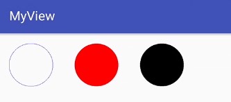
通過執行結果可以看到,貌似Paint.Style.FILL和Paint.Style.FILL_AND_STROKE其實並沒有什麼區別。
但是,如果把畫筆的寬度調寬一些:
mPaint.setStrokeWidth(50);

mPaint.setColor(Color.RED);
mPaint.setStyle(Paint.Style.FILL);
canvas.drawCircle(mLeftX, mLeftY, 50, mPaint);

mPaint.setColor(Color.BLACK);
mPaint.setStyle(Paint.Style.FILL_AND_STROKE);
canvas.drawCircle(mLeftX * 4, mLeftY, 50, mPaint);
執行結果:
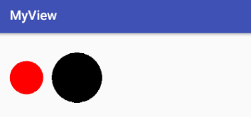
可以看出看來,FILL_AND_STROKE其實會把寬度一起填充。
setShadowLayer()
setShadowLayer(float radius, float dx, float dy, int shadowColor):
* radius:陰影傾斜度。
* dx:水平位移。
* dy:垂直位移。
* shadowColor:陰影顏色。
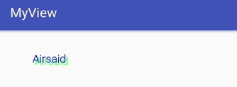
給文字繪製上陰影:
mPaint.setTextSize(50);
mPaint.setColor(Color.BLUE);
mPaint.setShadowLayer(5, 10, 10, Color.GREEN);
canvas.drawText("Airsaid", mLeftX, mLeftY, mPaint);
執行結果:
Canvas常用函式
Canvas作為畫布,含有繪製各種圖形的函式,下面根據具體圖形來分類進行詳細講解。
繪製背景
- drawColor(int):繪製畫布背景。
- drawRGB(int r, int g, int b):同上。
- drawARGB(int a, int r, int g, int b):同上,四個引數取值範圍0~255。
繪製一條直線
- drawLine(float startX, float startY,float stopX,float stopY,Paint paint):
- startX:開始x座標。
- startY:開始Y座標。
- stopX:結束x座標。
- stopY:結束Y座標。
- paint:繪製直線所用畫筆。
程式碼例項:
mPaint.setColor(Color.BLUE);
mPaint.setStrokeWidth(10);
canvas.drawLine(0, 0, getWidth(), 0, mPaint);
執行結果:

繪製多條直線
- drawLines(float[] pts, Paint paint):一般繪製多條直線。
- pts:座標點資料的集合,每4個為一組繪製一條直線。
- paint:繪製直線所用畫筆。
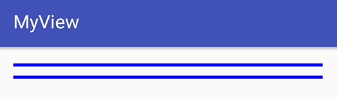
程式碼例項:
mPaint.setColor(Color.BLUE);
mPaint.setStrokeWidth(10);
float pts[] = {0, 10, getWidth(), 10, 0, 50, getWidth(), 50};
canvas.drawLines(pts, mPaint);
執行結果:
- drawLines(float[] pts, int offset, int count, Paint paint):有選擇的繪製多條直線。
- pts:座標點資料的集合,每4個為一組繪製一條直線。
- offset:跳過的資料個數,跳過的資料將不參與繪製過程。
- conunt:實際參與繪製的資料個數。
- paint:繪製直線所用畫筆。
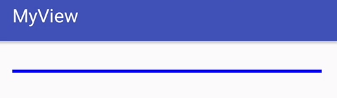
程式碼示例,跳過一條線的繪製:
mPaint.setColor(Color.BLUE);
mPaint.setStrokeWidth(10);
float pts[] = {0, 10, getWidth(), 10, 0, 50, getWidth(), 50};
canvas.drawLines(pts, 4, 4, mPaint);
執行結果:
繪製單點
- drawPoint(float x, float y,Paint paint):繪製一個點。
- x:點的x座標。
- y:點的y座標。
- paint:繪製點所用畫筆。
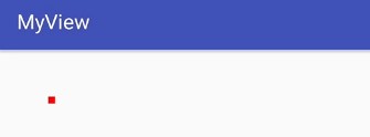
程式碼示例:
mPaint.setColor(Color.RED);
mPaint.setStrokeWidth(20);
canvas.drawPoint(100, 100, mPaint);
執行結果:
繪製多點
- drawPoints(float[] pts, Paint paint):繪製多個點。
- pts:座標點的資料集合,每兩個為一組繪製一個點。
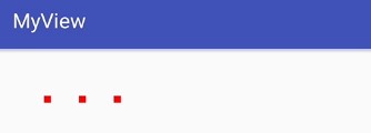
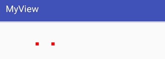
程式碼示例(繪製三個點):
- pts:座標點的資料集合,每兩個為一組繪製一個點。
mPaint.setColor(Color.RED);
mPaint.setStrokeWidth(20);
float pts[] = {100, 100, 200, 100, 300, 100};
canvas.drawPoints(pts, mPaint);
執行結果:
- drawPoints(float[] pts, int offset, int count, Paint paint): 有選擇的繪製多個點。
- pts:引數同上,其他引數同繪製多條線一樣。
程式碼示例(跳過第1個點,只繪製2個點):
- pts:引數同上,其他引數同繪製多條線一樣。
mPaint.setColor(Color.RED);
mPaint.setStrokeWidth(20);
float pts[] = {100, 100, 200, 100, 300, 100};
canvas.drawPoints(pts, 2, 4, mPaint);
執行結果:
繪製矩形
- drawRect(Rect r, Paint paint):根據傳入的Rect繪製矩形。
- drawRect(RectF rect, Paint paint):根據傳入的RectF繪製矩形。
- drawRect(float left, float top, float rigth, float bottom, Paint paint):直接傳入矩形的四個點來繪製矩形。
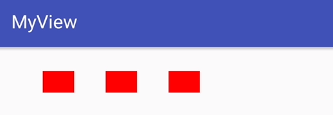
程式碼示例(分別使用以上函式繪製三個矩形):
mPaint.setColor(Color.RED);

Rect rect = new Rect(100, 30, 200, 100);
canvas.drawRect(rect, mPaint);

RectF rectF = new RectF(300, 30, 400, 100);
canvas.drawRect(rectF, mPaint);

canvas.drawRect(500, 30, 600, 100, mPaint);
其中Rect和RectF為矩形輔助類,可根據4個點構建一片矩形區域,用於幫助我們對矩形進行操作。
執行結果:
繪製圓角矩形
- drawRoundRect(RectF rect, float rx, float ry, Paint paint): 根據傳入的RectF繪製圓角矩形。
- rect:要繪製的矩形。
- rx:x軸圓角橢圓半徑。
- ry:y軸圓角橢圓半徑。
- drawRoundRect(float left, float top, float rigth, float bottom, float rx, float ry, Paint paint):直接傳入矩形的四個點來繪製圓角矩形,從API21開始提供。
引數同上。
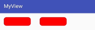
程式碼例項(根據以上函式分別繪製圓角矩形):
mPaint.setColor(Color.RED);
RectF rectF = new RectF(0, 0, 300, 100);
canvas.drawRoundRect(rectF, 30f, 30f, mPaint);

if (Build.VERSION.SDK_INT >= Build.VERSION_CODES.LOLLIPOP) {
    canvas.drawRoundRect(400f, 0f, 700f, 100f, 30f, 30f, mPaint);
}
其中,由於直接傳入矩形的四個點來繪製圓角矩形的函式是在API21才開始提供,所以進行了判斷。
執行結果:
繪製圓形
- drawCircle(float cx,float cy,float radius,Paint paint):
- cx:圓心點x軸座標。
- cy:圓心點y軸座標。
- radius:圓的半徑。
- paint:繪製圓形所用畫筆。
程式碼示例:
mPaint.setColor(Color.RED);
canvas.drawCircle(100f, 50f, 50f, mPaint);
執行結果:

繪製橢圓
- drawOval(RectF oval, Paint paint):根據矩形物件繪製橢圓。
- oval:矩形物件。橢圓根據該矩形物件生成,以矩形的長作為橢圓的x軸,寬為y軸。
- drawOval(float left, float top, float rigth, float bottom, Paint paint):直接傳入矩形的四個點來繪製橢圓,從API21開始提供。
引數同上。
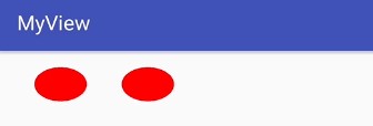
程式碼示例:
mPaint.setColor(Color.RED);
RectF rectF = new RectF(50, 0, 200, 100);
canvas.drawOval(rectF, mPaint);

if (Build.VERSION.SDK_INT >= Build.VERSION_CODES.LOLLIPOP) {
    canvas.drawOval(300, 0, 450, 100, mPaint);
}
執行結果:
繪製弧形
- drawArc(RectF oval, float startAngle, float sweepAngle, boolean useCenter, Paint paint):
- oval:矩形物件。
- startAngle:弧形開始的角度。
- sweepAngle:弧形持續的角度。
- useCenter:是否有弧形的兩邊。
- paint:繪製弧形的畫筆。
- drawArc(float left, float top, float rigth, float bottom,float startAngle, float sweepAngle, boolean useCenter, Paint paint):
引數同上。
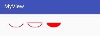
程式碼例項:
mPaint.setColor(Color.RED);
mPaint.setStrokeWidth(5);
mPaint.setStyle(Paint.Style.STROKE);
RectF rectF = new RectF(50, 0, 200, 100);
canvas.drawArc(rectF, 0f, 180f, false, mPaint);

RectF rectF2 = new RectF(250, 0, 400, 100);
canvas.drawArc(rectF2, 0f, 180f, true, mPaint);

RectF rectF3 = new RectF(450, 0, 600, 100);
mPaint.setStyle(Paint.Style.FILL);
canvas.drawArc(rectF3, 0f, 180f, true, mPaint);
執行結果: