
深度學習Tracking(1)——Learning to Track at 100 FPS with Deep Regression Networks(程式碼理解)
第一次看深度學習網路實現的工程程式碼,有很多內容和結構不理解,並且在Linux下跑網路工程程式碼沒有IDE,無法除錯,我也不知道在檢視函式的時候如何跳轉,因此看整個工程檔案十分麻煩。因此自己也是邊看邊查邊學。
下面開始解析該工程程式碼,可能存在一些偏差和錯誤,將會不斷學習和修正。
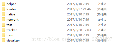
一、工程結構
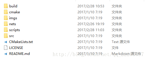
工程主目錄下有6個資料夾以及3個檔案。
CMakeLists.txt:
CMake是一個跨平臺的安裝(編譯)工具,可以用簡單的語句來描述所有平臺的安裝(編譯過程)。CMake的所有語句都寫在CMakeLists.txt檔案中,當CMakeList.txt檔案確定後,可以用ccmake命令對相關的變數值進行配置,這個命令必須指向CMakeList.txt所在的目錄。配置完成後,應用cmake命令生成相應的Makefile(在UNIX like系統下)或者project檔案(指定用Windows下的相應程式設計工具編譯時)。
詳細看博文:【
build資料夾:
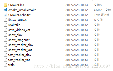
該資料夾內為編譯之後生成的一些檔案,具體我也不是很懂,之後再看。
cmake資料夾:
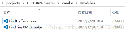
該資料夾是配置檔案,指向相應的caffe模型,配置工程所需的庫檔案。
FindTinyXML.cmake的功能之後再去了解吧。。。
imgs資料夾記憶體放的是一張論文中功能實現的截圖。
nets資料夾:
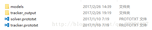
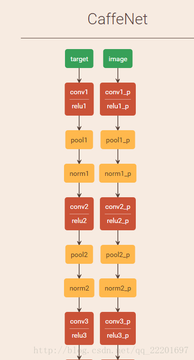
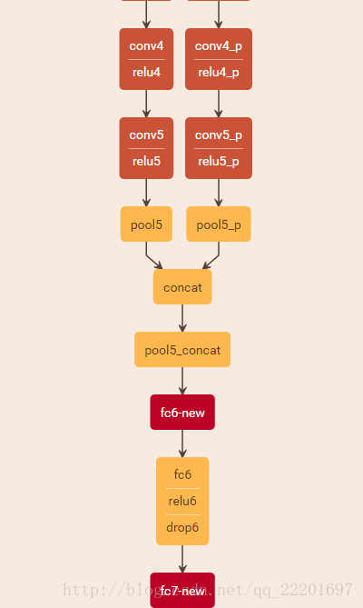
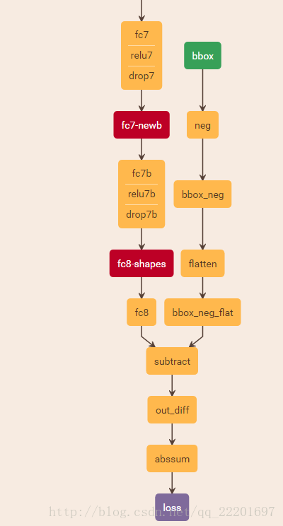
tracker.prototxt定義了網路的結構,利用netscope我們可以看到網路結構是這樣的,並不複雜。
solver.prototxt檔案是整個模型執行的引數配置檔案。
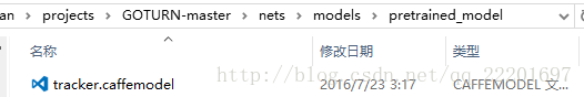
models裡是已經訓練好的網路模型:
tracker_output裡是工程的輸出檔案,包括videos等。
scripts檔案:
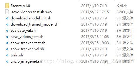
該資料夾內是執行程式的一些指令碼檔案。實現的功能包括下載模型初始化(download_model_init.sh),下載訓練好的模型(download_trained_model.sh),評估結果(evaluate_val.sh),儲存測試執行結果(save_videos_test.sh),追蹤過程展示(show_tracker_test.sh),追蹤過程驗證(show_tracker_val.sh),訓練(train.sh)以及解壓ImageNet(unzip_imagenet.sh)。還有一個資料夾Fscore_v1.0應該是計算Fscore時用到的相關檔案。
src資料夾:
該資料夾內為c++原始碼。
由於伺服器上執行無法實現視覺化,所以我按照原始碼文件的說明,將測試資料執行結果儲存下來(呼叫save_videos_test.sh指令碼檔案),然後觀察其performance。下面將按照執行的流程對部分程式碼進行解釋說明。
二、程式碼流程(根據需求呼叫的部分)
首先通過如下語句執行指令碼檔案以執行程式:
bash scripts/save_videos_test.sh /*/dataPackage/vot20141、因此,進入save_videos_test.sh檔案
#!/bin/bash

if [ -z "$1" ]
  then
    echo "No folder supplied!"
    echo "Usage: bash `basename "$0"` vot_videos_folder"
    exit
fi

# Choose which GPU the tracker runs on
GPU_ID=10

VIDEOS_FOLDER=$1

FOLDER=GOTURN1_test

DEPLOY_PROTO=nets/tracker.prototxt

CAFFE_MODEL=nets/models/pretrained_model/tracker.caffemodel

OUTPUT_FOLDER=nets/tracker_output/$FOLDER

echo "Saving output to " $OUTPUT_FILE

# Run tracker on test set and save vidoes
build/save_videos_vot $VIDEOS_FOLDER $DEPLOY_PROTO $CAFFE_MODEL $OUTPUT_FOLDER $GPU_ID
GPU_ID:這裡可以修改使用的GPU編號,由於伺服器上執行的程式較多,導致程式執行速度變慢,因此,要選擇一個空閒的GPU使用。(新開一個終端,輸入nvidia-smi就可以檢視GPU使用情況。)
VIDEOS_FOLDER:$1指的是第一個引數,即指令後面緊跟的第一個引數,這裡是輸入的視訊資料夾(事實上是影象資料夾);
DEPLOY_PROTO:該指令呼叫的模型,即網路結構
,但是存在未知引數。
CAFFE_MODEL:訓練好的網路模型,經過訓練,引數都已確定。
指令碼檔案的最後呼叫了save_videos_vot.cpp,因此下面進入該檔案。
2、save_videos_vot.cpp
該檔案在test資料夾下,程式碼內容如下:
#include <string>
#include <boost/lexical_cast.hpp>
#include <boost/filesystem.hpp>
#include <opencv/cv.h>
#include <opencv2/core/core.hpp>
#include <opencv2/highgui/highgui.hpp>
#include "helper/high_res_timer.h"
#include "network/regressor.h"
#include "loader/loader_alov.h"
#include "loader/loader_vot.h"
#include "tracker/tracker.h"
#include "tracker/tracker_manager.h"
using std::string;
int main (int argc, char *argv[]) {
if (argc < 6) {
std::cerr << "Usage: " << argv[0]
<< " videos_folder deploy.prototxt network.caffemodel"
<< " output_folder gpu_id" << std::endl;
return 1;
}
::google::InitGoogleLogging(argv[0]);
string videos_folder = argv[1];
string test_proto = argv[2];
string caffe_model = argv[3];
string output_folder = argv[4];
int gpu_id = atoi(argv[5]);
boost::filesystem::create_directories(output_folder);
const bool do_train = false;
Regressor regressor(test_proto, caffe_model, gpu_id, do_train);
// Time how long tracking takes.
HighResTimer hrt_total("Total evaluation (including loading videos)");
hrt_total.start();
// Get videos.
std::vector<Video> videos;
LoaderVOT loader(videos_folder);
videos = loader.get_videos();
// Create a tracker object.
const bool show_intermediate_output = false;
Tracker tracker(show_intermediate_output);
// Track all objects in all videos and save the output.
const bool save_videos = true;
TrackerTesterAlov tracker_tester(videos, save_videos, ®ressor, &tracker, output_folder);
tracker_tester.TrackAll();
// Print the timing information.
hrt_total.stop();
hrt_total.print();
return 0;
}
函式開始,先建立了一個Regressor物件並利用引數(現有網路模型)對其進行初始化,此處設定為test模式。進入Regressor類看一下:
- 2.1 、regressor.cpp
Regressor::Regressor(const string& deploy_proto,
                     const string& caffe_model,
                     const int gpu_id,
                     const bool do_train)
  : num_inputs_(kNumInputs),
    caffe_model_(caffe_model),
    modified_params_(false)
{
  SetupNetwork(deploy_proto, caffe_model, gpu_id, do_train);
}
上面為Regressor類的建構函式,呼叫SetupNetwork函式來設定網路。SetupNetwork函式如下:
void Regressor::SetupNetwork(const string& deploy_proto,
                             const string& caffe_model,
                             const int gpu_id,
                             const bool do_train) {
#ifdef CPU_ONLY
  printf("Setting up Caffe in CPU mode\n");
  caffe::Caffe::set_mode(caffe::Caffe::CPU);
#else
  printf("Setting up Caffe in GPU mode with ID: %d\n", gpu_id);
  caffe::Caffe::SetDevice(gpu_id);
  caffe::Caffe::set_mode(caffe::Caffe::GPU);
#endif

  if (do_train) {
    printf("Setting phase to train\n");
    net_.reset(new Net<float>(deploy_proto, caffe::TRAIN));
  } else {
    printf("Setting phase to test\n");
    net_.reset(new Net<float>(deploy_proto, caffe::TEST));
  }

  if (caffe_model != "NONE") {
    net_->CopyTrainedLayersFrom(caffe_model_);
  } else {
    printf("Not initializing network from pre-trained model\n");
  }

  //CHECK_EQ(net_->num_inputs(), num_inputs_) << "Network should have exactly " << num_inputs_ << " inputs.";
  CHECK_EQ(net_->num_outputs(), 1) << "Network should have exactly one output.";

  Blob<float>* input_layer = net_->input_blobs()[0];

  printf("Network image size: %d, %d\n", input_layer->width(), input_layer->height());

  num_channels_ = input_layer->channels();
  CHECK(num_channels_ == 3 || num_channels_ == 1)
    << "Input layer should have 1 or 3 channels.";
  input_geometry_ = cv::Size(input_layer->width(), input_layer->height());

  // Load the binaryproto mean file.
  SetMean();
}
設定網路實現的主要功能是:在螢幕輸出當前使用的GPU,當前為訓練還是測試階段,是否有可用的訓練好的模型等。
這邊定義了一個Blob型別的指標input_layer,指向前面的net_的input_blobs()物件的第0個數據。這邊的net_應該是通過前面的CopyTrainedLayersFrom(caffe_model_)進行初始化,即初始化為已訓練好的模型,因此這邊後面輸出的“Network image size”應該指的是已訓練好的模型對應的影象的size吧?因為我使用的測試資料的size都不是其輸出的227x227的。我猜想對於我輸入的影象資料,網路應該會對其進行一個reshape或者resize之類的操作吧?後面再看看。
該函式中呼叫的最後一個函式是SetMean()。該函式的作用為設定一個均值影象,即對於一幅3通道的影象,設定其三個通道值,使其表現出色彩均衡。函式體定義如下:
void Regressor::SetMean() {
  // Set the mean image.
  mean_ = cv::Mat(input_geometry_, CV_32FC3, cv::Scalar(104, 117, 123));
}
上述操作,即Regressor類的建構函式,對於該工程呼叫的模型進行了一些初始化操作。
之後是定義了時間物件,為了後續計算程式執行時間。然後載入需要測試的影象檔案(這裡用的是videos)。
下一步是建立一個tracker物件。
- 2.2 、tracker.cpp
首先將輸出中間結果的flag置為false,即不輸出中間結果。
建立了一個tracker物件。
- 2.3 、tracker_manager.cpp
然後定義了一個TrackerTesterAlov物件,對於輸入資料進行測試。
TrackerTesterAlov派生於TrackerManager類。
TrackerTesterAlov::TrackerTesterAlov(const std::vector<Video>& videos,
                                     const bool save_videos,
                                     RegressorBase* regressor, Tracker* tracker,
                                     const std::string& output_folder) :
  TrackerManager(videos, regressor, tracker),
  output_folder_(output_folder),
  hrt_("Tracker"),
  total_ms_(0),
  num_frames_(0),
  save_videos_(save_videos)
{
}
上面是TrackerTesterAlov的建構函式,save_videos_vot.cpp在呼叫該函式時,引數videos為從資料夾中獲取到的videos,save_videos置為true,regressor為前面建立過的regressor,tracker為前面建立的Tracker物件,以及最後輸出的路徑。
引數後面緊跟著的是建構函式初始值列表,為新建立物件的資料成員賦初值。
這邊有呼叫了其父類TrackerManager的建構函式:
TrackerManager::TrackerManager(const std::vector<Video>& videos,
                               RegressorBase* regressor, Tracker* tracker) :
  videos_(videos),
  regressor_(regressor),
  tracker_(tracker)
{
}
初始化完成之後,開始tracking操作,呼叫TrackAll函式。
void TrackerManager::TrackAll(const size_t start_video_num, const int pause_val) {
  // Iterate over all videos and track the target object in each.
  for (size_t video_num = start_video_num; video_num < videos_.size(); ++video_num) {
    // Get the video.
    const Video& video = videos_[video_num];

    // Perform any pre-processing steps on this video.
    VideoInit(video, video_num);

    // Get the first frame of this video with the initial ground-truth bounding box (to initialize the tracker).
    int first_frame;
    cv::Mat image_curr;
    BoundingBox bbox_gt;
    video.LoadFirstAnnotation(&first_frame, &image_curr, &bbox_gt);

    // Initialize the tracker.
    tracker_->Init(image_curr, bbox_gt, regressor_);//image_curr:the first frame; bbox_gt: the groundtruth box of the first frame

    // Iterate over the remaining frames of the video.
    for (size_t frame_num = first_frame + 1; frame_num < video.all_frames.size(); ++frame_num) {

      // Get image for the current frame.
      // (The ground-truth bounding box is used only for visualization).
      const bool draw_bounding_box = false;
      const bool load_only_annotation = false;
      cv::Mat image_curr;
      BoundingBox bbox_gt;
      bool has_annotation = video.LoadFrame(frame_num,
                                            draw_bounding_box,
                                            load_only_annotation,
                                            &image_curr, &bbox_gt);

      // Get ready to track the object.
      SetupEstimate();

      // Track and estimate the target's bounding box location in the current image.
      // Important: this method cannot receive bbox_gt (the ground-truth bounding box) as an input.
      BoundingBox bbox_estimate_uncentered;
      tracker_->Track(image_curr, regressor_, &bbox_estimate_uncentered);

      // Process the output (e.g. visualize / save results).
      ProcessTrackOutput(frame_num, image_curr, has_annotation, bbox_gt,
                           bbox_estimate_uncentered, pause_val);
    }
    PostProcessVideo();
  }
  PostProcessAll();
}
呼叫該函式時,將start_video_num置為0,pause_val置為1,即迭代所有的videos並且track其中的目標。
1、首先利用for迴圈,獲取資料夾內所有的videos;
2、然後利用VideoInit函式對videos進行初始化,包括從資料夾獲取video的名稱,建立資料夾以存放輸出結果,獲取輸出結果影象的尺寸以及建立一個video_writer物件以儲存videos。
3、獲取該視訊的第一幀以及其對應的初始目標所在框。這裡呼叫了LoadFirstAnnotation函式來載入initial groundtruth。對應的函式定義在loader資料夾下的video.cpp檔案內。
void Video::LoadFirstAnnotation(int* first_frame, cv::Mat* image,
                               BoundingBox* box) const {
  LoadAnnotation(0, first_frame, image, box);
}

void Video::LoadAnnotation(const int annotation_index,
                          int* frame_num,
                          cv::Mat* image,
                          BoundingBox* box) const {
  // Get the annotation corresponding to this index.
  const Frame& annotated_frame = annotations[annotation_index];

  // Get the frame number corresponding to this annotation.
  *frame_num = annotated_frame.frame_num;

  *box = annotated_frame.bbox;

  const string& video_path = path;
  const vector<string>& image_files = all_frames;

  if (image_files.empty()) {
    printf("Error - no image files for video at path: %s\n", path.c_str());
    return;
  } else if (*frame_num >= image_files.size()) {
    printf("Cannot find frame: %d; only %zu image files were found at %s\n", *frame_num, image_files.size(), path.c_str());
    return;
  }

  // Load the image corresponding to this annotation.
  const string& image_file = video_path + "/" + image_files[*frame_num];
  *image = cv::imread(image_file);

  if (!image->data) {
    printf("Could not find file: %s\n", image_file.c_str());
  }
}
4、下面就利用獲取到的當前幀影象即第一幀影象、當前幀目標框即初始目標所在框和定義好的迴歸器對於tracker進行初始化。
這裡進入tracker資料夾下的tracker.cpp檔案。對應的函式定義為:
void Tracker::Init(const cv::Mat& image, const BoundingBox& bbox_gt,
                   RegressorBase* regressor) {
  image_prev_ = image;
  bbox_prev_tight_ = bbox_gt;

  // Predict in the current frame that the location will be approximately the same
  // as in the previous frame.
  // TODO - use a motion model?
  bbox_curr_prior_tight_ = bbox_gt;

  // Initialize the neural network.
  regressor->Init();
}
這裡假設當前幀中目標位置是和前一幀中目標位置非常相近,即運動很小的情況下。這邊對於神經網路又進行了一次初始化。防止引數修改。
void Regressor::Init() {
  if (modified_params_ ) {
    printf("Reloading new params\n");
    net_->CopyTrainedLayersFrom(caffe_model_);
    modified_params_ = false;
  }
}
5、遍歷該video的後續幀,獲取當前幀影象以及目標標記框的groundtruth(如果有的話),設定時間,準備開始tracking操作。
呼叫Tracker類的Track函式,實現track功能。函式定義如下:
void Tracker::Track(const cv::Mat& image_curr, RegressorBase* regressor,
                    BoundingBox* bbox_estimate_uncentered) {
  // Get target from previous image.
  cv::Mat target_pad;
  CropPadImage(bbox_prev_tight_, image_prev_, &target_pad);

  // Crop the current image based on predicted prior location of target.
  cv::Mat curr_search_region;
  BoundingBox search_location;
  double edge_spacing_x, edge_spacing_y;
  CropPadImage(bbox_curr_prior_tight_, image_curr, &curr_search_region, &search_location, &edge_spacing_x, &edge_spacing_y);

  // Estimate the bounding box location of the target, centered and scaled relative to the cropped image.
  BoundingBox bbox_estimate;
  regressor->Regress(image_curr, curr_search_region, target_pad, &bbox_estimate);

  // Unscale the estimation to the real image size.
  BoundingBox bbox_estimate_unscaled;
  bbox_estimate.Unscale(curr_search_region, &bbox_estimate_unscaled);

  // Find the estimated bounding box location relative to the current crop.
  bbox_estimate_unscaled.Uncenter(image_curr, search_location, edge_spacing_x, edge_spacing_y, bbox_estimate_uncentered);

  if (show_tracking_) {
    ShowTracking(target_pad, curr_search_region, bbox_estimate);
  }

  // Save the image.
  image_prev_ = image_curr;

  // Save the current estimate as the location of the target.
  bbox_prev_tight_ = *bbox_estimate_uncentered;

  // Save the current estimate as the prior prediction for the next image.
  // TODO - replace with a motion model prediction?
  bbox_curr_prior_tight_ = *bbox_estimate_uncentered;
}
該函式實現的功能包含以下操作:
- (1)裁剪出影象中目標區域,即從前一幀中獲取目標所在patch;
- (2)基於前一幀影象中目標位置,對於當前幀影象進行裁剪;
由於這邊定義了一個乍看不是很明白的變數,因此,把這個函式貼出來看一下其函式體。
void CropPadImage(const BoundingBox& bbox_tight, const cv::Mat& image, cv::Mat* pad_image,
                  BoundingBox* pad_image_location, double* edge_spacing_x, double* edge_spacing_y) {
  // Crop the image based on the bounding box location, adding some padding.

  // Get the location of the cropped and padded image.
  ComputeCropPadImageLocation(bbox_tight, image, pad_image_location);

  // Compute the ROI, ensuring that the crop stays within the boundaries of the image.
  const double roi_left = std::min(pad_image_location->x1_, static_cast<double>(image.cols - 1));
  const double roi_bottom = std::min(pad_image_location->y1_, static_cast<double>(image.rows - 1));
  const double roi_width = std::min(static_cast<double>(image.cols), std::max(1.0, ceil(pad_image_location->x2_ - pad_image_location->x1_)));
  const double roi_height = std::min(static_cast<double>(image.rows), std::max(1.0, ceil(pad_image_location->y2_ - pad_image_location->y1_)));

  // Crop the image based on the ROI.
  cv::Rect myROI(roi_left, roi_bottom, roi_width, roi_height);
  cv::Mat cropped_image = image(myROI);

  // Now we need to place the crop in a new image of the appropriate size,
  // adding a black border where necessary to account for edge effects.

  // Make a new image to store the output.
  // The new image should have size: get_output_width(), get_output_height(), but
  // to be safe we ensure that the output is not smaller than roi_width, roi_height.
  const double output_width = std::max(ceil(bbox_tight.compute_output_width()), roi_width);
  const double output_height = std::max(ceil(bbox_tight.compute_output_height()), roi_height);
  cv::Mat output_image = cv::Mat(output_height, output_width, image.type(), cv::Scalar(0, 0, 0));

  // Compute the location to place the crop so that it will be centered at the
  // center of the bounding box (accounting for edge effects).

  // Get the amount that the output "sticks out" beyond the left and bottom edges of the image.
  // This might be 0, but it might be > 0 if the output is near the edge of the image.
  *edge_spacing_x = std::min(bbox_tight.edge_spacing_x(), static_cast<double>(output_image.cols - 1));
  *edge_spacing_y = std::min(bbox_tight.edge_spacing_y(), static_cast<double>(output_image.rows - 1));

  // Get the location within the output to put the cropped image (accounting for edge effects).
  cv::Rect output_rect(*edge_spacing_x, *edge_spacing_y, roi_width, roi_height);
  cv::Mat output_image_roi = output_image(output_rect);

  // Copy the cropped image to the specified location within the output.
  // Without edge effects, this will fill the output.
  // With edge effects, this will comprise a subset of the output, with black
  // being placed around the crop to account for edge effects.
  cropped_image.copyTo(output_image_roi);

  // Set the output.
  *pad_image = output_image;
}
這裡的引數bbox_tight為前一幀的目標所在框,image為當前幀,pad_image用來存放裁剪出的區域影象,pad_image_location用目標狂來表示裁剪出的影象塊,edge_spacing_x和edge_spacing_y表示該影象塊的左上角點的座標。但是這個座標不是之前裁剪區域對應的左上角座標,而是可能比其稍大一些的output框對應的左上角。這邊有點不是很理解。
下面呼叫ComputeCropPadImageLocation函式來計算裁剪出的影象及其位置。
之後計算興趣域,保證裁剪區域在影象邊界範圍內。
然後將上一步處理完成的區域裁剪出來生成剪裁後的影象。
之後將剪裁出來的影象放置於一幅有著合適尺寸的新影象中,對於會產生邊緣效應的地方,加上一個黑色邊框。生成合適尺寸的影象,用於存放該輸出。
計算出cropped image的合適位置,使得其中心位於bounding box的中心。
double BoundingBox::edge_spacing_x() const {
  const double output_width = compute_output_width();
  const double bbox_center_x = get_center_x();

  // Compute the amount that the output "sticks out" beyond the edge of the image (edge effects).
  // If there are no edge effects, we would have output_width / 2 < bbox_center_x, but if the crop is near the left
  // edge of the image then we would have output_width / 2 > bbox_center_x, with the difference
  // being the amount that the output "sticks out" beyond the edge of the image.
  return std::max(0.0, output_width / 2 - bbox_center_x);
}
該函式首先計算該bounding box的寬度,然後獲取該bounding box的中心點的x座標,然後計算bounding box的左側邊的x座標值,應該是大於0的。這個值即為返回的edge_spacing_x。
6、進入正題,開始迴歸估計本幀中目標所在框的位置。
進入該函式看一下:
Regress函式:
void Regressor::Regress(const cv::Mat& image_curr,
                        const cv::Mat& image, const cv::Mat& target,
                        BoundingBox* bbox) {
  assert(net_->phase() == caffe::TEST);

  // Estimate the bounding box location of the target object in the current image.
  std::vector<float> estimation;
  Estimate(image, target, &estimation);

  // Wrap the estimation in a bounding box object.
  *bbox = BoundingBox(estimation);
}
Estimate函式:
void Regressor::Estimate(const cv::Mat& image, const cv::Mat& target, std::vector<float>* output) {
  assert(net_->phase() == caffe::TEST);

  // Reshape the input blobs to be the appropriate size.
  Blob<float>* input_target = net_->input_blobs()[0];
  input_target->Reshape(1, num_channels_,
                       input_geometry_.height, input_geometry_.width);

  Blob<float>* input_image = net_->input_blobs()[1];
  input_image->Reshape(1, num_channels_,
                       input_geometry_.height, input_geometry_.width);

  Blob<float>* input_bbox = net_->input_blobs()[2];
  input_bbox->Reshape(1, 4, 1, 1);

  // Forward dimension change to all layers.
  net_->Reshape();

  // Process the inputs so we can set them.
  std::vector<cv::Mat> target_channels;
  std::vector<cv::Mat> image_channels;
  WrapInputLayer(&target_channels, &image_channels);

  // Set the inputs to the network.
  Preprocess(image, &image_channels);
  Preprocess(target, &target_channels);

  // Perform a forward-pass in the network.
  net_->ForwardPrefilled();

  // Get the network output.
  GetOutput(output);
}
該函式的第一步是將輸入影象reshape成合適的大小,與我之前猜測的一致。
這邊又遇到問題了,對於Blob這種資料格式不夠理解。