
OPENCV3.0 雙目立體標定
阿新 • • 發佈:2019-02-09
這裡是在上一篇單目標定的基礎上拓展來的進行雙目標定的程式。
在這個程式裡面,預設是先對兩個攝像頭分別進行了單目標定的,也就是說相機的內參數和畸變向量是知道了的。
所以在進行標定的時候,引數選擇的是CALIB_USE_INTRINSIC_GUESS。
此程式依然是使用系統自帶的標定的圖片,其路徑在opencv的安裝目錄下:opencv\sources\samples\data。
本程式最終的輸出影象為
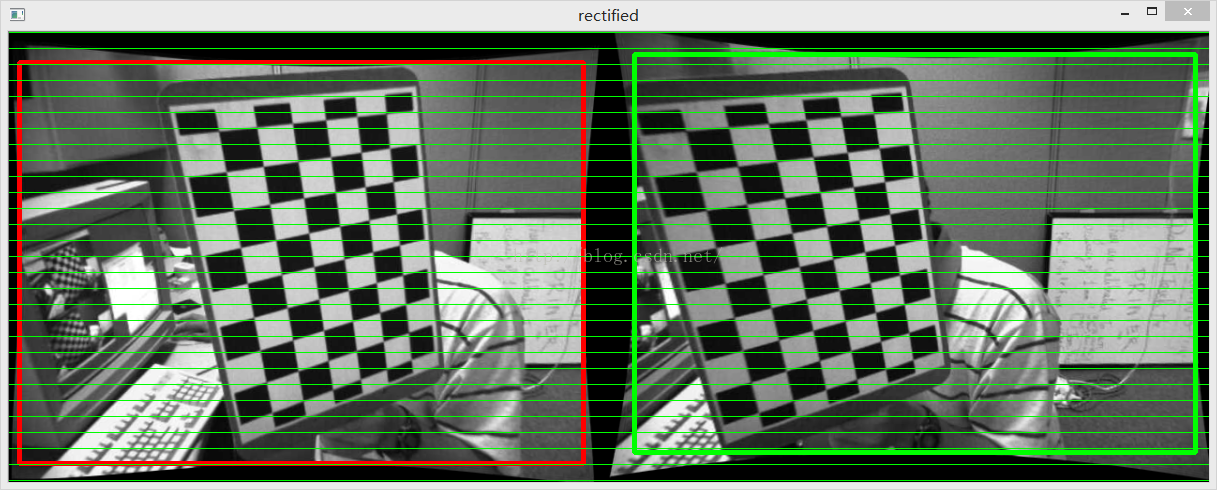
上圖就是左右相機的影象經過行對準之後的結果。
具體的程式碼如下:
// stereoCalibration.cpp : 定義控制檯應用程式的入口點。
//
//在進行雙目攝像頭的標定之前,最好事先分別對兩個攝像頭進行單目視覺的標定
//分別確定兩個攝像頭的內參矩陣,然後再開始進行雙目攝像頭的標定
//在此例程中是先對兩個攝像頭進行單獨標定(見上一篇單目標定文章),然後在進行立體標定

#include "stdafx.h"
#include <opencv2/opencv.hpp>
#include <highgui.hpp>
#include "cv.h"
#include <cv.hpp>
#include <iostream>

using namespace std;
using namespace cv;

const int imageWidth = 640;								//攝像頭的解析度
const int imageHeight = 480;
const int boardWidth = 9;								//橫向的角點數目
const int boardHeight = 6;								//縱向的角點資料
const int boardCorner = boardWidth * boardHeight;		//總的角點資料
const int frameNumber = 13;								//相機標定時需要採用的影象幀數
const int squareSize = 20;								//標定板黑白格子的大小 單位mm
const Size boardSize = Size(boardWidth, boardHeight);	//
Size imageSize = Size(imageWidth, imageHeight);

Mat R, T, E, F;											//R 旋轉向量 T平移向量 E本徵矩陣 F基礎矩陣
vector<Mat> rvecs;									    //旋轉向量
vector<Mat> tvecs;										//平移向量
vector<vector<Point2f>> imagePointL;				    //左邊攝像機所有照片角點的座標集合
vector<vector<Point2f>> imagePointR;					//右邊攝像機所有照片角點的座標集合
vector<vector<Point3f>> objRealPoint;					//各副影象的角點的實際物理座標集合


vector<Point2f> cornerL;								//左邊攝像機某一照片角點座標集合
vector<Point2f> cornerR;								//右邊攝像機某一照片角點座標集合

Mat rgbImageL, grayImageL;
Mat rgbImageR, grayImageR;

Mat Rl, Rr, Pl, Pr, Q;									//校正旋轉矩陣R,投影矩陣P 重投影矩陣Q (下面有具體的含義解釋)
Mat mapLx, mapLy, mapRx, mapRy;							//對映表
Rect validROIL, validROIR;								//影象校正之後,會對影象進行裁剪,這裡的validROI就是指裁剪之後的區域

/*
事先標定好的左相機的內參矩陣
fx 0 cx
0 fy cy
0 0  1
*/
Mat cameraMatrixL = (Mat_<double>(3, 3) << 532.782, 0,       532.904,
										  0,       342.505, 233.876,
										  0,       0,       1);
Mat distCoeffL = (Mat_<double>(5, 1) << -0.28095, 0.0255745, 0.00122226, -0.000137736, 0.162946);
/*
事先標定好的右相機的內參矩陣
fx 0 cx
0 fy cy
0 0  1
*/
Mat cameraMatrixR = (Mat_<double>(3, 3) << 532.782, 0,       532.904,
											0,      342.505, 233.876,
											0,		0,		 1);
Mat distCoeffR = (Mat_<double>(5, 1) << -0.28095, 0.0255745, 0.00122226, -0.000137736, 0.162946);


/*計算標定板上模組的實際物理座標*/
void calRealPoint(vector<vector<Point3f>>& obj, int boardwidth, int boardheight, int imgNumber, int squaresize)
{
	//	Mat imgpoint(boardheight, boardwidth, CV_32FC3,Scalar(0,0,0));
	vector<Point3f> imgpoint;
	for (int rowIndex = 0; rowIndex < boardheight; rowIndex++)
	{
		for (int colIndex = 0; colIndex < boardwidth; colIndex++)
		{
			//	imgpoint.at<Vec3f>(rowIndex, colIndex) = Vec3f(rowIndex * squaresize, colIndex*squaresize, 0);
			imgpoint.push_back(Point3f(rowIndex * squaresize, colIndex * squaresize, 0));
		}
	}
	for (int imgIndex = 0; imgIndex < imgNumber; imgIndex++)
	{
		obj.push_back(imgpoint);
	}
}

void outputCameraParam(void)
{
	/*儲存資料*/
	/*輸出資料*/
	FileStorage fs("intrinsics.yml", FileStorage::WRITE);
	if (fs.isOpened())
	{
		fs << "cameraMatrixL" << cameraMatrixL << "cameraDistcoeffL" << distCoeffL <<"cameraMatrixR" << cameraMatrixR << "cameraDistcoeffR" << distCoeffR;
		fs.release();
		cout << "cameraMatrixL=:" << cameraMatrixL <<endl<< "cameraDistcoeffL=:" << distCoeffL <<endl<<"cameraMatrixR=:" << cameraMatrixR <<endl<< "cameraDistcoeffR=:" << distCoeffR<<endl;
	}
	else
	{
		cout << "Error: can not save the intrinsics!!!!!" << endl;
	}

	fs.open("extrinsics.yml", FileStorage::WRITE);
	if (fs.isOpened())
	{
		fs << "R" << R << "T" << T << "Rl" << Rl << "Rr" << Rr << "Pl" << Pl << "Pr" << Pr << "Q" << Q;
		cout << "R=" << R << endl << "T=" << T << endl << "Rl=" << Rl << endl << "Rr=" << Rr << endl << "Pl=" << Pl << endl << "Pr=" << Pr << endl << "Q=" << Q << endl;
		fs.release();
	}
	else
		cout << "Error: can not save the extrinsic parameters\n";
}


int _tmain(int argc, _TCHAR* argv[])
{
	Mat img;
	int goodFrameCount = 0;
	namedWindow("ImageL");
	namedWindow("ImageR");
	cout << "按Q退出 ..." << endl;
	while (goodFrameCount < frameNumber)
	{
		char filename[100];
		/*讀取左邊的影象*/
		sprintf_s(filename, "image\\left%02d.jpg", goodFrameCount + 1);
		rgbImageL = imread(filename, CV_LOAD_IMAGE_COLOR);
		cvtColor(rgbImageL, grayImageL, CV_BGR2GRAY);

		/*讀取右邊的影象*/
		sprintf_s(filename, "image\\right%02d.jpg", goodFrameCount + 1);
		rgbImageR = imread(filename, CV_LOAD_IMAGE_COLOR);
		cvtColor(rgbImageR, grayImageR, CV_BGR2GRAY);

		bool isFindL, isFindR;

		isFindL = findChessboardCorners(rgbImageL, boardSize, cornerL);
		isFindR = findChessboardCorners(rgbImageR, boardSize, cornerR);
		if (isFindL == true && isFindR == true)	 //如果兩幅影象都找到了所有的角點 則說明這兩幅影象是可行的
		{
			/*
			Size(5,5) 搜尋視窗的一半大小
			Size(-1,-1) 死區的一半尺寸
			TermCriteria(CV_TERMCRIT_EPS | CV_TERMCRIT_ITER, 20, 0.1)迭代終止條件
			*/
			cornerSubPix(grayImageL, cornerL, Size(5, 5), Size(-1, -1), TermCriteria(CV_TERMCRIT_EPS | CV_TERMCRIT_ITER, 20, 0.1));
			drawChessboardCorners(rgbImageL, boardSize, cornerL, isFindL);
			imshow("chessboardL", rgbImageL);
			imagePointL.push_back(cornerL);


			cornerSubPix(grayImageR, cornerR, Size(5, 5), Size(-1, -1), TermCriteria(CV_TERMCRIT_EPS | CV_TERMCRIT_ITER, 20, 0.1));
			drawChessboardCorners(rgbImageR, boardSize, cornerR, isFindR);
			imshow("chessboardR", rgbImageR);
			imagePointR.push_back(cornerR);

			/*
			本來應該判斷這兩幅影象是不是好的,如果可以匹配的話才可以用來標定
			但是在這個例程當中,用的影象是系統自帶的影象,都是可以匹配成功的。
			所以這裡就沒有判斷
			*/
			//string filename = "res\\image\\calibration";
			//filename += goodFrameCount + ".jpg";
			//cvSaveImage(filename.c_str(), &IplImage(rgbImage));		//把合格的圖片儲存起來
			goodFrameCount++;
			cout << "The image is good" << endl;
		}
		else
		{
			cout << "The image is bad please try again" << endl;
		}

		if (waitKey(10) == 'q')
		{
			break;
		}
	}

	/*
	計算實際的校正點的三維座標
	根據實際標定格子的大小來設定
	*/
	calRealPoint(objRealPoint, boardWidth, boardHeight, frameNumber, squareSize);
	cout << "cal real successful" << endl;

	/*
		標定攝像頭
		由於左右攝像機分別都經過了單目標定
		所以在此處選擇flag = CALIB_USE_INTRINSIC_GUESS
	*/
	double rms = stereoCalibrate(objRealPoint, imagePointL, imagePointR,
		cameraMatrixL, distCoeffL,
		cameraMatrixR, distCoeffR,
		Size(imageWidth, imageHeight), R, T, E, F,
		CALIB_USE_INTRINSIC_GUESS,
		TermCriteria(TermCriteria::COUNT + TermCriteria::EPS, 100, 1e-5));

	cout << "Stereo Calibration done with RMS error = " << rms << endl;

	/*
	立體校正的時候需要兩幅影象共面並且行對準 以使得立體匹配更加的可靠
	使得兩幅影象共面的方法就是把兩個攝像頭的影象投影到一個公共成像面上,這樣每幅影象從本影象平面投影到公共影象平面都需要一個旋轉矩陣R
	stereoRectify 這個函式計算的就是從影象平面投影都公共成像平面的旋轉矩陣Rl,Rr。 Rl,Rr即為左右相機平面行對準的校正旋轉矩陣。
	左相機經過Rl旋轉,右相機經過Rr旋轉之後,兩幅影象就已經共面並且行對準了。
	其中Pl,Pr為兩個相機的投影矩陣,其作用是將3D點的座標轉換到影象的2D點的座標:P*[X Y Z 1]' =[x y w]
	Q矩陣為重投影矩陣,即矩陣Q可以把2維平面(影象平面)上的點投影到3維空間的點:Q*[x y d 1] = [X Y Z W]。其中d為左右兩幅影象的時差
	*/
	stereoRectify(cameraMatrixL, distCoeffL, cameraMatrixR, distCoeffR, imageSize, R, T, Rl, Rr, Pl, Pr, Q,
				  CALIB_ZERO_DISPARITY,-1,imageSize,&validROIL,&validROIR);
	/*
	根據stereoRectify 計算出來的R 和 P 來計算影象的對映表 mapx,mapy
	mapx,mapy這兩個對映表接下來可以給remap()函式呼叫,來校正影象,使得兩幅影象共面並且行對準
	ininUndistortRectifyMap()的引數newCameraMatrix就是校正後的攝像機矩陣。在openCV裡面,校正後的計算機矩陣Mrect是跟投影矩陣P一起返回的。
	所以我們在這裡傳入投影矩陣P,此函式可以從投影矩陣P中讀出校正後的攝像機矩陣
	*/
	initUndistortRectifyMap(cameraMatrixL, distCoeffL, Rl, Pr, imageSize, CV_32FC1, mapLx, mapLy);
	initUndistortRectifyMap(cameraMatrixR, distCoeffR, Rr, Pr, imageSize, CV_32FC1, mapRx, mapRy);


	Mat rectifyImageL, rectifyImageR;
	cvtColor(grayImageL, rectifyImageL, CV_GRAY2BGR);
	cvtColor(grayImageR, rectifyImageR, CV_GRAY2BGR);

	imshow("Rectify Before", rectifyImageL);

	/*
	經過remap之後,左右相機的影象已經共面並且行對準了
	*/
	remap(rectifyImageL, rectifyImageL, mapLx, mapLy, INTER_LINEAR);
	remap(rectifyImageR, rectifyImageR, mapRx, mapRy, INTER_LINEAR);

	imshow("ImageL", rectifyImageL);
	imshow("ImageR", rectifyImageR);

	/*儲存並輸出資料*/
	outputCameraParam();

	/*
		把校正結果顯示出來
		把左右兩幅影象顯示到同一個畫面上
		這裡只顯示了最後一副影象的校正結果。並沒有把所有的影象都顯示出來
	*/
	Mat canvas;
	double sf;
	int w, h;
	sf = 600. / MAX(imageSize.width, imageSize.height);
	w = cvRound(imageSize.width * sf);
	h = cvRound(imageSize.height * sf);
	canvas.create(h, w * 2, CV_8UC3);

	/*左影象畫到畫布上*/
	Mat canvasPart = canvas(Rect(w*0, 0, w, h));								//得到畫布的一部分
	resize(rectifyImageL, canvasPart, canvasPart.size(), 0, 0, INTER_AREA);		//把影象縮放到跟canvasPart一樣大小
	Rect vroiL(cvRound(validROIL.x*sf), cvRound(validROIL.y*sf),				//獲得被擷取的區域
		      cvRound(validROIL.width*sf), cvRound(validROIL.height*sf));
	rectangle(canvasPart, vroiL, Scalar(0, 0, 255), 3, 8);						//畫上一個矩形

	cout << "Painted ImageL" << endl;

	/*右影象畫到畫布上*/
	canvasPart = canvas(Rect(w, 0, w, h));										//獲得畫布的另一部分
	resize(rectifyImageR, canvasPart, canvasPart.size(), 0, 0, INTER_LINEAR);
	Rect vroiR(cvRound(validROIR.x * sf), cvRound(validROIR.y*sf),
			  cvRound(validROIR.width * sf), cvRound(validROIR.height * sf));
	rectangle(canvasPart, vroiR, Scalar(0, 255, 0), 3, 8);

	cout << "Painted ImageR" << endl;

	/*畫上對應的線條*/
	for (int i = 0; i < canvas.rows;i+=16)
		line(canvas, Point(0, i), Point(canvas.cols, i), Scalar(0, 255, 0), 1, 8);

	imshow("rectified", canvas);

	cout << "wait key" << endl;
	waitKey(0);
	system("pause");
	return 0;
}