
晶片驅動之充電晶片2
充電晶片4054學習手冊
- 晶片封裝
- 管腳介紹
- 晶片應用電路
晶片封裝
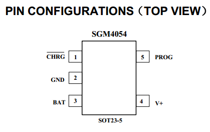
管腳介紹
| NAME | FUNCTION |
|---|---|
| CHRG | Open-Drain Charger Status indication pin. When the battery is charging, the CHRG pin is pulled low by an internal N-channel MOSFET. When the charge cycle is completed, a weak pull-down of approximately 20μA is connected to the CHRG pin, indicating an “AC present” condition. When the SGM4054 detects an undervoltage lockout condition, CHRG is forced high impedance. |
| BAT | Charge Current Output pin, connecting with Li-ion battery. Provides charge to 4.2V. An internal precision resistor divider from this pin sets the float voltage which is disconnected in shutdown mode. |
| V+ | Positive Input Supply Voltage. Provides power to the charger. V+ can range from 4.25V to 6.5V and should be bypassed with at least a 1μF capacitor. When V+ drops to within 54mV of the BAT pin voltage, the SGM4054 enters shutdown mode, dropping IBAT to less than 3μA. |
| PROG | Charge Current Program, Charge Current Monitor and Shutdown control Pin. The charge current is programmed by connecting a 1% resistor from RPROG pin to ground. When charging in constant-current mode, this pin servos to 1V. In all modes, the voltage on this pin can be used to measure the charge current using the following formula: IBAT = (VPROG/RPROG) • 1000 The PROG pin can also be used to shut down the charger. Disconnecting the program resistor from ground allows a 3uAcurrent to pull this pin to High When it reaches the 1.23V shutdown threshold voltage, the charger enters shutdown mode, charging stops and the input supply current drops to 25μA, this pin is also clamped to approximately 2.4V. Driving this pin to voltages beyond the clamp voltage will draw currents as high as 1.5mA. Reconnecting RPROG to ground will return the charger to normal operation. |
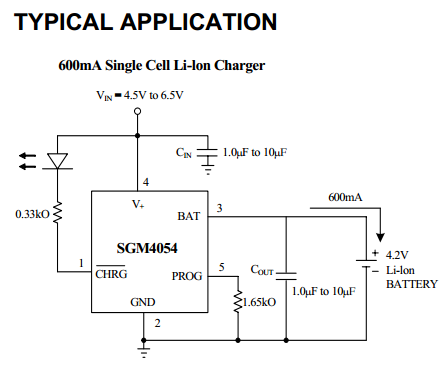
晶片應用電路
典型應用
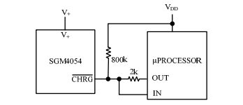
擴充套件應用
The charge status output has three different states: strong pull-down (~10mA), weak pull-down (~20µA) and high impedance. The strong pull-down state indicates that the SGM4054 is in a charge cycle. Once the charge cycle has terminated, the pin state is determined by undervoltage lockout conditions. A weak pull-down indicates that V+ meets the UVLO conditions and the SGM4054 is ready to charge. High impedance indicates that the SGM4054 is in undervoltage lockout mode: either V+ is less than 100mV above the BAT pin voltage or insufficient voltage is applied to the V+ pin. A microprocessor can be used to distinguish between these three states—this method is discussed in the Applications Information section.
To detect when the SGM4054 is in charge mode, force the digital output pin (OUT) high and measure the voltage at the CHGR pin. The N-channel MOSFET will pull the pin voltage low even with the 2k pull-up resistor. Once the charge cycle terminates, the N-channel MOSFET is turned off and a 20µA current source is connected to the CHGR pin. The IN pin will then be pulled high by the 2k pull-up resistor. To determine if there is a weak pull-down current, the OUT pin should be forced to a high impedance state. The weak current source will pull the IN pin low through the 800k resistor; if CHGR is high impedance, the IN pin will be pulled high, indicating that the part is in a UVLO state.
1. 當充電時,強下拉電流使得IN管教監測到低電平;當充滿時弱下拉電流為20uA,此時上拉2K電阻只能分壓40mV,IN監測到的是高電平則認為充飽了。
2. 當充飽時開啟監測是否移除充電樁的操作,OUT配置為高阻,若沒有移除充電樁,弱下拉電流20uA乘以800K上拉電阻,分壓接近VDD電壓,IN輸入電壓為低電平;若移除了充電樁,CHGR為高阻態,IN輸入電壓為高電平。
3. OUT輸出為高,若檢測到輸入為高,則認為在充電狀態;若輸入為低,則進入判斷是充飽了還是已經移除了充電器;把OUT置為高阻態,若IN檢測為低,則認為充飽了,若檢測為高則認為充電樁移除了。