Canny邊緣檢測演算法(基於OpenCV的Java實現)
目錄
- Canny邊緣檢測演算法(基於OpenCV的Java實現)
- 緒論
- Canny邊緣檢測演算法的發展歷史
- Canny邊緣檢測演算法的處理流程
- 用高斯濾波器平滑影象
- 彩色RGB影象轉換為灰度影象
- 一維,二維高斯函式及分佈
- 生成高斯濾波卷積核
- 單色高斯濾波與彩色高斯濾波
- 用Sobel等梯度運算元計算梯度幅值和方向
- 梯度
- 影象灰度值的梯度的簡單求法
- 使用Sobel運算元來計算梯度的大小及方向:
- 對梯度幅值進行非極大值抑制
- 雙閾值檢測
- 抑制孤立低閾值點
- Reference
Canny邊緣檢測演算法(基於OpenCV的Java實現)
緒論
最近在學習ORB的過程中又仔細學習了Canny,故寫下此篇筆記,以作總結。
Canny邊緣檢測演算法的發展歷史
Canny邊緣檢測於1986年由JOHN CANNY首次在論文《A Computational Approach to Edge Detection》中提出,就此拉開了Canny邊緣檢測演算法的序幕。
Canny邊緣檢測是從不同視覺物件中提取有用的結構資訊並大大減少要處理的資料量的一種技術,目前已廣泛應用於各種計算機視覺系統。Canny發現,在不同視覺系統上對邊緣檢測的要求較為類似,因此,可以實現一種具有廣泛應用意義的邊緣檢測技術。邊緣檢測的一般標準包括:
- 以低的錯誤率檢測邊緣,也即意味著需要儘可能準確的捕獲影象中儘可能多的邊緣。
- 檢測到的邊緣應精確定位在真實邊緣的中心。
- 影象中給定的邊緣應只被標記一次,並且在可能的情況下,影象的噪聲不應產生假的邊緣。
為了滿足這些要求,Canny使用了變分法。Canny檢測器中的最優函式使用四個指數項的和來描述,它可以由高斯函式的一階導數來近似。
在目前常用的邊緣檢測方法中,Canny邊緣檢測演算法是具有嚴格定義的,可以提供良好可靠檢測的方法之一。由於它具有滿足邊緣檢測的三個標準和實現過程簡單的優勢,成為邊緣檢測最流行的演算法之一。
Canny邊緣檢測演算法的處理流程
Canny邊緣檢測演算法可以分為以下5個步驟:
- 使用高斯濾波器,以平滑影象,濾除噪聲。
- 計算影象中每個畫素點的梯度強度和方向。
- 應用非極大值(Non-Maximum Suppression)抑制,以消除邊緣檢測帶來的雜散響應。
- 應用雙閾值(Double-Threshold)檢測來確定真實的和潛在的邊緣。
- 通過抑制孤立的弱邊緣最終完成邊緣檢測。
下面詳細介紹每一步的實現思路。
用高斯濾波器平滑影象
高斯濾波是一種線性平滑濾波,適用於消除高斯噪聲,特別是對抑制或消除服從正態分佈的噪聲非常有效。濾波可以消除或降低影象中噪聲的影響,使用高斯濾波器主要是基於在濾波降噪的同時也可以最大限度保留邊緣資訊的考慮。
高斯濾波實現步驟:
彩色RGB影象轉換為灰度影象
邊緣檢測是基於對影象灰度差異運算實現的,所以如果輸入的是RGB彩色影象,需要先進行灰度圖的轉換。
RGB轉換成灰度影象的一個常用公式是:
\[
Gray = R*0.299 + G*0.587 + B*0.114
\]
注意一般情況下影象處理中彩色影象各分量的排列順序是B、G、R。
RGB原影象: 轉換後的灰度圖:


Java程式碼呼叫系統庫實現:
public static Mat RGB2Gray(Mat image) {
    // Gray = R*0.299 + G*0.587 + B*0.114
    Mat gray = new Mat();
    Imgproc.cvtColor(image, gray, Imgproc.COLOR_BGR2GRAY);
    return gray;
}
一維,二維高斯函式及分佈
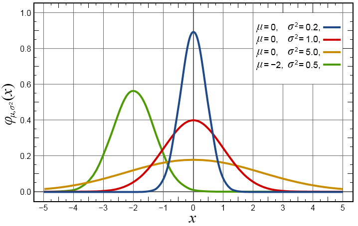
一維高斯函式表述為:
\[
G(x) = \frac {1}{\sqrt {2\pi}\sigma}\exp(-\frac {(x-\mu_x)^2}{2\sigma^2})
\]
對應圖形:
二維高斯函式表述為:
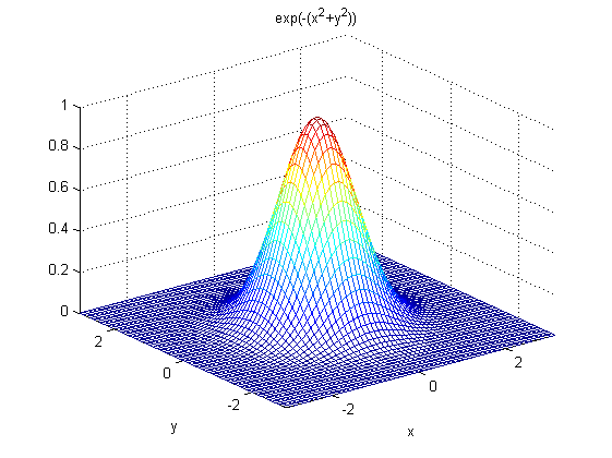
\[
G(x) = \frac {1}{ {2\pi}\sigma^2}\exp(-\frac {(x-\mu_x)^2+(y-\mu_y)^2}{2\sigma^2})
\]
對應圖形:
一些重要特性說明:
- 一維二維高斯函式中\(μ\)是服從正態分佈的隨機變數的均值,稱為期望或均值影響正態分佈的位置,實際的影象處理應用中一般取\(μ=0;~σ\)是標準差,\(σ^2\)是隨機變數的方差,\(σ\)定義了正態分佈資料的離散程度,\(σ\)越大,資料分佈越分散,σ越小,資料分佈越集中。
在圖形或濾波效果上表現為:\(σ\)越大,曲線越扁平,高斯濾波器的頻帶就越寬,平滑程度就越好,\(σ\)越小,曲線越瘦高,高斯濾波的頻帶就越窄,平滑程度也越弱;
- 二維高斯函式具有旋轉對稱性,即濾波器在各個方向上的平滑程度是相同的.一般來說,一幅影象的邊緣方向是事先不知道的,因此,在濾波前是無法確定一個方向上比另一方向上需要更多的平滑.旋轉對稱性意味著高斯平滑濾波器在後續邊緣檢測中不會偏向任一方向;
- 高斯函式是單值函式。這表明,高斯濾波器用畫素鄰域的加權均值來代替該點的畫素值,而每一鄰域畫素點權值是隨該點與中心點的距離單調增減的。這一性質是很重要的,因為邊緣是一種影象區域性特徵,如果平滑運算對離運算元中心很遠的畫素點仍然有很大作用,則平滑運算會使影象失真;
- 相同條件下,高斯卷積核的尺寸越大,影象的平滑效果越好,表現為影象越模糊,同時影象細節丟失的越多;尺寸越小,平滑效果越弱,影象細節丟失越少;
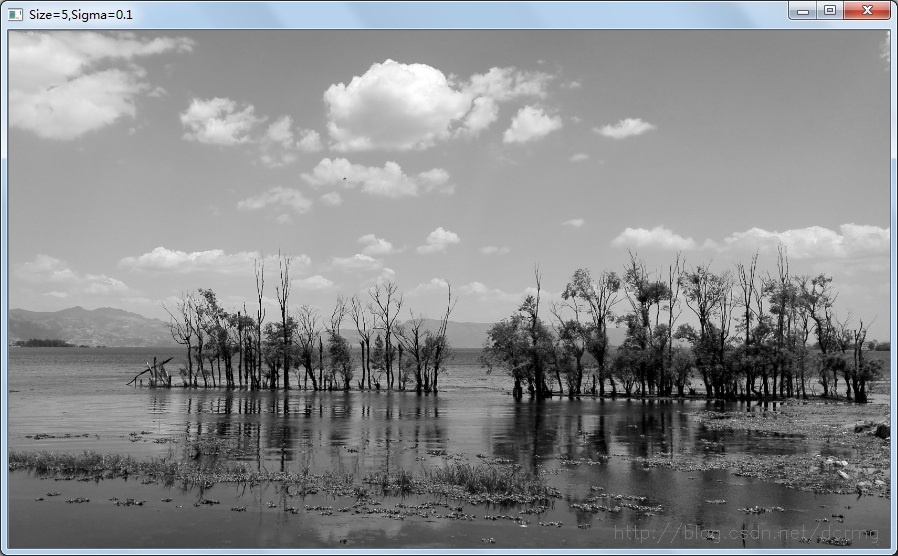
以下對比一下不同大小標準差\(σ\)(Sigma)對影象平滑的影響:
原圖:

卷積核尺寸5*5,σ=0.1:
卷積核尺寸5*5,σ=1:
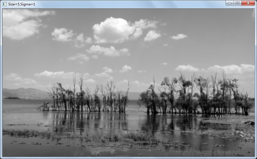
對比可以看到,Sigma(σ)越大,平滑效果越明顯。
生成高斯濾波卷積核
濾波的主要目的是降噪,一般的影象處理演算法都需要先進行降噪。而高斯濾波主要使影象變得平滑(模糊),同時也有可能增大了邊緣的寬度。
高斯函式是一個類似與正態分佈的中間大兩邊小的函式。
對於一個位置(m,n)的畫素點,其灰度值(這裡只考慮二值圖)為f(m,n)。
那麼經過高斯濾波後的灰度值將變為:
\[
g_\sigma(m,n)=\frac 1 {2\pi\sigma^2} \exp(-\frac {m^2+n^2}{2\sigma^2})f(m,n)
\]
其中,
\[
\frac 1 {{2\pi\sigma^2}} \exp(-\frac {m^2+n^2}{2\sigma^2})
\]
是二元高斯函式。
為了儘可能減少噪聲對邊緣檢測結果的影響,所以必須濾除噪聲以防止由噪聲引起的錯誤檢測。為了平滑影象,使用高斯濾波器與影象進行卷積,該步驟將平滑影象,以減少邊緣檢測器上明顯的噪聲影響。大小為(2k+1)x(2k+1)的高斯濾波器核的生成方程式由下式給出:

下面是一個sigma = 1.4,尺寸為3x3的高斯卷積核的例子(需要注意歸一化):
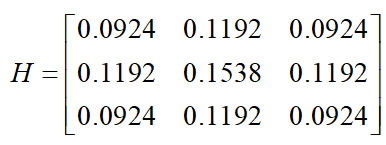
若影象中一個3x3的視窗為A,要濾波的畫素點為e,則經過高斯濾波之後,畫素點e的亮度值為:

其中*為卷積符號,sum表示矩陣中所有元素相加求和。
重要的是需要理解,高斯卷積核大小的選擇將影響Canny檢測器的效能。尺寸越大,檢測器對噪聲的敏感度越低,但是邊緣檢測的定位誤差也將略有增加。一般5x5是一個比較不錯的trade off。
public static double[][] getGaussianArray(int size, double sigma) {
    double[][] array = new double[size][size];
    double center_i, center_j;
    if (size % 2 == 1) { center_i = (double) (size / 2); center_j = (double) (size / 2); }
    else { center_i = (double) (size / 2) - 0.5; center_j = (double) (size / 2) - 0.5; }
    double sum = 0.0;
    for (int i = 0; i < size; i ++)
            for (int j = 0; j < size; j ++) {
                array[i][j] = Math.exp((-1.0) * ((i - center_i) * (i - center_i) + (j - center_j) * (j - center_j)) / 2.0 / sigma / sigma);
                sum += array[i][j];
            }
    for (int i = 0; i < size; i ++)
            for (int j = 0; j < size; j++)
                array[i][j] /= sum;
    return array;
}
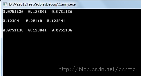
Sigma為1時,求得的3*3大小的高斯卷積核引數為:
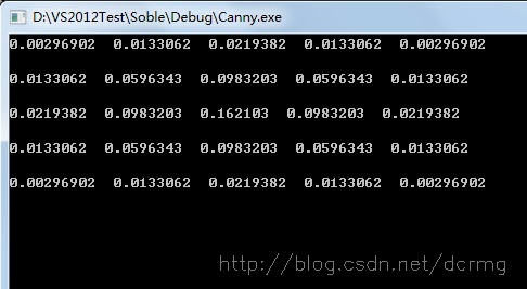
Sigma為1,5*5大小的高斯卷積核引數為:
在計算出高斯濾波卷積核之後就是用這個卷積核來掃過整張影象,對每個畫素點進行加權平均。
單色高斯濾波與彩色高斯濾波
加入了多執行緒的優化,程式碼實現:
public static Mat greyGaussianFilter(Mat src, double[][] array, int size) throws InterruptedException {
    Mat temp = src.clone();
    final CountDownLatch latch = new CountDownLatch(src.rows());
    for (int i = 0; i < src.rows(); i ++) {
            int finalI = i;
            new Thread(() -> {
                for (int j = 0; j < src.cols(); j ++)
                        if (finalI > (size / 2) - 1 && j > (size / 2) - 1 &&
                            finalI < src.rows() - (size / 2) && j < src.cols() - (size / 2)) {
                            double sum = 0.0;
                            for (int k = 0; k < size; k++)
                                    for (int l = 0; l < size; l++)
                                        sum += src.get(finalI - k + size / 2, j - l + size / 2)[0] * array[k][l];
                            temp.put(finalI, j, sum);
                        }
                latch.countDown();
            }).start();
    }
    latch.await();
    return temp;
}

public static Mat colorGaussianFilter(Mat src, int size, double sigma) throws InterruptedException {
    // return variable
    Mat ret = new Mat();
    // list for merge and split
    List<Mat> channels = new ArrayList<>();
    List<Mat> new_channels = new ArrayList<>();
    Map<Integer, Mat> temp_channels = new TreeMap<>();
    // split into 3 channels (r, g, b)
    Core.split(src, channels);
    // get gaussion array
    double[][] array = SmartGaussian.getGaussianArray(size, sigma);
    // multi-thread
    final CountDownLatch latch = new CountDownLatch(channels.size());
    channels.forEach(mat -> {
            new Thread(() -> {
                Mat tmp = new Mat();
                try {
                        tmp = SmartGaussian.greyGaussianFilter(mat, array, size);
                } catch (InterruptedException e) {
                        e.printStackTrace();
                }
                temp_channels.put(channels.indexOf(mat), tmp);
                latch.countDown();
            }).start();
    });
    latch.await();
    for (int i = 0; i < channels.size(); i ++)
          new_channels.add(temp_channels.get(i));
    Core.merge(new_channels, ret);
    return ret;
}效果圖:(左圖為原圖,中間為上面的實現,右邊是OpenCV實現)

用Sobel等梯度運算元計算梯度幅值和方向
梯度
梯度的本意是一個向量(向量),表示某一函式在該點處的方向導數沿著該方向取得最大值,即函式在該點處沿著該方向(此梯度的方向)變化最快,變化率最大(為該梯度的模)。
設二元函式:
\[
z=f(x,y)
\]
在平面區域D上具有一階連續偏導數,則對於每一個點\(P(x,y)\)都可定出一個向量:
\[
\Big\{\frac {∂ f}{∂ x},\frac {∂ f} {∂ y} \Big\}
=f_x(x,y)\vec i + f_y(x,y)\vec j
\]
該函式就稱為函式\(z=f(x,y)\)在點\(P(x,y)\)的梯度,記作\(\text{grad}~f(x,y)\)或\(\nabla f(x,y)\),即有:
\[
\text{grad}~f(x,y)=\nabla f(x,y)=\Big\{\frac {∂ f}{∂ x},\frac {∂ f} {∂ y} \Big\}
=f_x(x,y)\vec i + f_y(x,y)\vec j
\]
其中 稱為(二維的)向量微分運算元或Nabla運算元。
設 是方向\(l\)上的單位向量,則


由於當方向\(l\)與梯度方向一致時,有 。
。
所以當\(l\)與梯度方向一致時,方向導數 有最大值,且最大值為梯度的模,即
 。
。
因此說,函式在一點沿梯度方向的變化率最大,最大值為該梯度的模。
影象灰度值的梯度的簡單求法
影象灰度值的梯度可以使用最簡單的一階有限差分來進行近似,使用以下影象在x和y方向上偏導數的兩個矩陣:
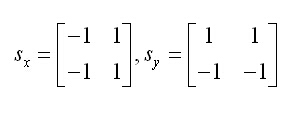
計算公式為:

其中\(f\)為影象灰度值,\(P[i,j]\)代表\([i,j]\)在\(X\)方向梯度幅值,\(Q[i,j]\)代表\([i,j]\)在\(Y\)方向的梯度幅值,\(M[i,j]\)是該點幅值,\(\theta[i,j]\)是梯度方向,也就是角度。
使用Sobel運算元來計算梯度的大小及方向:
影象中的邊緣可以指向各個方向,因此Canny演算法使用四個運算元來檢測影象中的水平、垂直和對角邊緣。邊緣檢測的運算元(如Roberts,Prewitt,Sobel等)返回水平Gx和垂直Gy方向的一階導數值,由此便可以確定畫素點的梯度G和方向theta 。
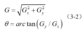
其中G為梯度強度, theta表示梯度方向,arctan為反正切函式。下面以Sobel運算元為例講述如何計算梯度強度和方向。
x和y方向的Sobel運算元分別為:

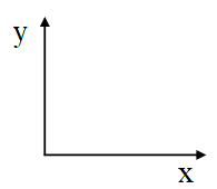
其中Sx表示x方向的Sobel運算元,用於檢測y方向的邊緣; Sy表示y方向的Sobel運算元,用於檢測x方向的邊緣(邊緣方向和梯度方向垂直)。在直角座標系中,Sobel運算元的方向如下圖所示。
若影象中一個3x3的視窗為A,要計算梯度的畫素點為e,則和Sobel運算元進行卷積之後,畫素點e在x和y方向的梯度值分別為:
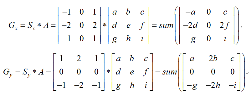
其中*為卷積符號,sum表示矩陣中所有元素相加求和。根據公式(3-2)便可以計算出畫素點e的梯度和方向。
下面是Sobel運算元求梯度的java實現:
package edu.sfls.Jeff.JavaDev.CVLib;

import org.opencv.core.Core;
import org.opencv.core.CvType;
import org.opencv.core.Mat;

import java.util.concurrent.CountDownLatch;

public class SmartSobel {

    private Mat gradientX = new Mat(), gradientY = new Mat(), gradientXY = new Mat();
    private double[][] pointDirection;

    public SmartSobel() {}

    public void compute(Mat image) throws InterruptedException {
        pointDirection = new double[image.rows()][image.cols()];
        for (int i = 0; i < image.rows(); i ++)
            for (int j = 0; j < image.cols(); j ++)
                pointDirection[i][j] = 0;
        gradientX = Mat.zeros(image.size(), CvType.CV_32SC1);
        gradientY = Mat.zeros(image.size(), CvType.CV_32SC1);
        gradientXY = Mat.zeros(image.size(), CvType.CV_32SC1);
        final CountDownLatch latch = new CountDownLatch(image.rows() - 2);
        for (int i = 1; i < image.rows() - 1; i ++) {
            int finalI = i;
            new Thread(() -> {
                for (int j = 1; j < image.cols() - 1; j++) {
                    double gX = (-1) * image.get(finalI - 1, j - 1)[0] +
                            1 * image.get(finalI - 1, j + 1)[0] +
                            (-2) * image.get(finalI, j - 1)[0] +
                            2 * image.get(finalI, j + 1)[0] +
                            (-1) * image.get(finalI + 1, j - 1)[0] +
                            1 * image.get(finalI + 1, j + 1)[0];
                    double gY = 1 * image.get(finalI - 1, j - 1)[0] +
                            2 * image.get(finalI - 1, j)[0] +
                            1 * image.get(finalI - 1, j + 1)[0] +
                            (-1) * image.get(finalI + 1, j - 1)[0] +
                            (-2) * image.get(finalI + 1, j)[0] +
                            (-1) * image.get(finalI + 1, j + 1)[0];
                    gradientY.put(finalI, j, Math.abs(gY));
                    gradientX.put(finalI, j, Math.abs(gX));
                    gradientXY.put(finalI, j, Math.sqrt(gX * gX + gY * gY));
                    // 防止除以0的情況發生
                    if (gX == 0) gX = 0.00000000000000001;
                    pointDirection[finalI][j] = Math.atan(gY / gX);
                }
                latch.countDown();
            }).start();
        }
        latch.await();
    }

    public void convert() {
        Core.convertScaleAbs(gradientX, gradientX);
        Core.convertScaleAbs(gradientY, gradientY);
        Core.convertScaleAbs(gradientXY, gradientXY);
    }

    public Mat getGradientX() { return this.gradientX; }

    public Mat getGradientY() { return this.gradientY; }

    public Mat getGradientXY() { return this.gradientXY; }

    public double[][] getPointDirection() { return this.pointDirection; }

}
由於這裡使用的是\(Math.tan()\),所以最終的角度是對映在\([-\frac \pi 2, \frac \pi 2]\)的範圍之內的。如果使用\(Math.tan2()\)會對映到\([-\pi,\pi]\)的範圍內,並且無需考慮符號影響,更加精確。但是這裡我們並不關心另外的一個\(\pi\)的情況,我們只關心其所在直線(這在後文中會提到,也就是非極大值抑制),所以無需多考慮。
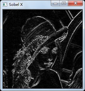
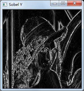
X方向梯度圖: Y方向梯度圖:
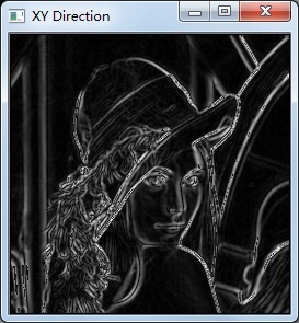
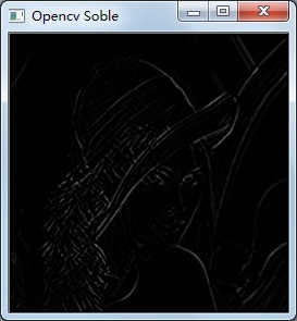
X、Y方向梯度融合效果: Opencv Sobel函式效果:
對梯度幅值進行非極大值抑制
非極大值抑制是一種邊緣稀疏技術,非極大值抑制的作用在於“瘦”邊。對影象進行梯度計算後,僅僅基於梯度值提取的邊緣仍然很模糊。對於標準3,對邊緣有且應當只有一個準確的響應。而非極大值抑制則可以幫助將區域性最大值之外的所有梯度值抑制為0,對梯度影象中每個畫素進行非極大值抑制的演算法是:
1) 將當前畫素的梯度強度與沿正負梯度方向上的兩個畫素進行比較。
2) 如果當前畫素的梯度強度與另外兩個畫素相比最大,則該畫素點保留為邊緣點,否則該畫素點將被抑制。
通常為了更加精確的計算,在跨越梯度方向的兩個相鄰畫素之間使用線性插值來得到要比較的畫素梯度,現舉例如下:
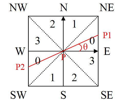
圖3-2 梯度方向分割
如圖3-2所示,將梯度分為8個方向,分別為E、NE、N、NW、W、SW、S、SE,其中0代表\(0^\circ\sim45^\circ\),1代表\(45^\circ\sim90^\circ\),2代表\(-90^\circ\sim-45^\circ\),3代表\(-45^\circ\sim0^\circ\)。畫素點P的梯度方向為\(\theta\),則畫素點P1和P2的梯度線性插值為:
\[
\tan \theta = G_y ~/~G_x \\
G_{p1} = (1-\tan\theta)\times E + \tan\theta \times NE \\
G_{p2} = (1-\tan\theta)\times W + \tan\theta \times SW \\
\]
上面也只是圖中的情況,具體情況如下:
\[
\theta \in [0, \frac \pi 4]:
\begin {cases}
G_{p1} = (1-\tan\theta)\times E + \tan\theta \times NE \\
G_{p2} = (1-\tan\theta)\times W + \tan\theta \times SW
\end {cases}\\\theta \in [\frac \pi 4, \frac \pi 2]:
\begin {cases}
G_{p1} = (1-\tan\theta)\times N + \tan\theta \times NE \\
G_{p2} = (1-\tan\theta)\times S + \tan\theta \times SW
\end {cases}\\\theta \in [-\frac \pi 4, 0]:
\begin {cases}
G_{p1} = (1-\tan(-\theta))\times E + \tan(-\theta) \times SE \\
G_{p2} = (1-\tan(-\theta))\times W + \tan(-\theta) \times NW
\end {cases}\\\theta \in [-\frac \pi 2, -\frac \pi 4]:
\begin {cases}
G_{p1} = (1-\tan(-\theta))\times S + \tan(-\theta) \times SE \\
G_{p2} = (1-\tan(-\theta))\times N + \tan(-\theta) \times NW
\end {cases}\\
\]
因此非極大值抑制的虛擬碼描寫如下:
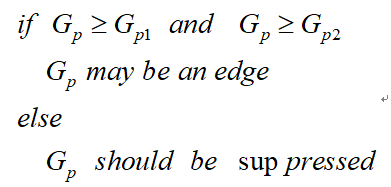
需要注意的是,如何標誌方向並不重要,重要的是梯度方向的計算要和梯度運算元的選取保持一致。
Java實現:
package edu.sfls.Jeff.JavaDev.CVLib;

import org.opencv.core.CvType;
import org.opencv.core.Mat;

import java.util.concurrent.CountDownLatch;

public class SmartNMS {

    public static Mat NMS(Mat gradientImage, double[][] pointDirection) throws InterruptedException {
        Mat outputImage = gradientImage.clone();
        final CountDownLatch latch = new CountDownLatch(gradientImage.rows() - 2);
        for (int i = 1; i < gradientImage.rows() - 1; i ++) {
            int finalI = i;
            new Thread(() -> {
                for (int j = 1; j < gradientImage.cols() - 1; j ++) {
                    double GP = gradientImage.get(finalI, j)[0],
                            E = gradientImage.get(finalI, j + 1)[0],
                            NE = gradientImage.get(finalI - 1, j + 1)[0],
                            N = gradientImage.get(finalI - 1, j)[0],
                            NW = gradientImage.get(finalI - 1, j - 1)[0],
                            W = gradientImage.get(finalI, j - 1)[0],
                            SW = gradientImage.get(finalI + 1, j - 1)[0],
                            S = gradientImage.get(finalI + 1, j)[0],
                            SE = gradientImage.get(finalI + 1, j + 1)[0];
                    double GP1 = 0, GP2 = 0;
                    double theta = pointDirection[finalI][j];
                    if (theta >= 0 && theta <= Math.PI / 4) {
                        GP1 = E * (1 - Math.tan(theta)) + NE * Math.tan(theta);
                        GP2 = W * (1 - Math.tan(theta)) + SW * Math.tan(theta);
                    } else if (theta > Math.PI / 4) {
                        GP1 = N * (1 - 1 / Math.tan(theta)) + NE * 1 / Math.tan(theta);
                        GP2 = S * (1 - 1 / Math.tan(theta)) + SW * 1 / Math.tan(theta);
                    } else if (theta < 0 && theta >= -Math.PI / 4) {
                        GP1 = E * (1 - Math.tan(-theta)) + SE * Math.tan(-theta);
                        GP2 = W * (1 - Math.tan(-theta)) + NW * Math.tan(-theta);
                    } else {
                        GP1 = S * (1 - 1 / Math.tan(-theta)) + SE * 1 / Math.tan(-theta);
                        GP2 = N * (1 - 1 / Math.tan(-theta)) + NW * 1 / Math.tan(-theta);
                    }
                    if (GP < GP1 || GP < GP2) outputImage.put(finalI, j, 0);
                }
                latch.countDown();
            }).start();
        }
        latch.await();
        return outputImage;
    }

}
雙閾值檢測
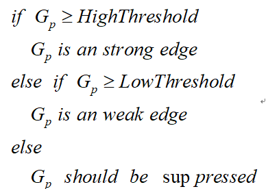
在施加非極大值抑制之後,剩餘的畫素可以更準確地表示影象中的實際邊緣。然而,仍然存在由於噪聲和顏色變化引起的一些邊緣畫素。為了解決這些雜散響應,必須用弱梯度值過濾邊緣畫素,並保留具有高梯度值的邊緣畫素,可以通過選擇高低閾值來實現。如果邊緣畫素的梯度值高於高閾值,則將其標記為強邊緣畫素;如果邊緣畫素的梯度值小於高閾值並且大於低閾值,則將其標記為弱邊緣畫素;如果邊緣畫素的梯度值小於低閾值,則會被抑制。閾值的選擇取決於給定輸入影象的內容。
雙閾值檢測的虛擬碼描寫如下:
抑制孤立低閾值點
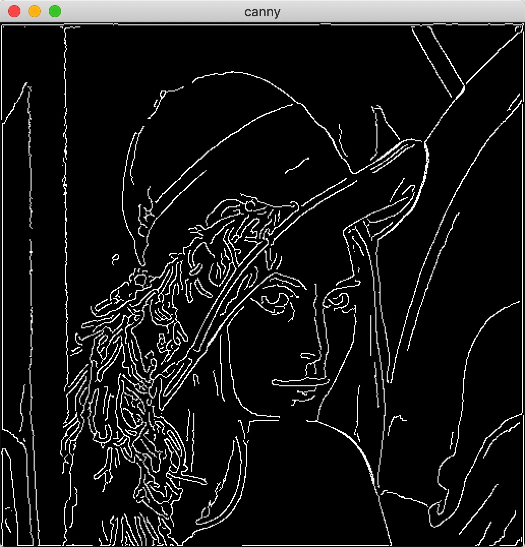
到目前為止,被劃分為強邊緣的畫素點已經被確定為邊緣,因為它們是從影象中的真實邊緣中提取出來的。然而,對於弱邊緣畫素,將會有一些爭論,因為這些畫素可以從真實邊緣提取也可以是因噪聲或顏色變化引起的。為了獲得準確的結果,應該抑制由後者引起的弱邊緣。通常,由真實邊緣引起的弱邊緣畫素將連線到強邊緣畫素,而噪聲響應未連線。為了跟蹤邊緣連線,通過檢視弱邊緣畫素及其8個鄰域畫素,只要其中一個為強邊緣畫素,則該弱邊緣點就可以保留為真實的邊緣。
抑制孤立邊緣點的虛擬碼描述如下:

實現:(使用遞迴)
package edu.sfls.Jeff.JavaDev.CVLib;

import org.opencv.core.Mat;

import java.util.ArrayList;
import java.util.List;

public class SmartCanny {

    private List<Integer[]> highPoints = new ArrayList<Integer[]>();

    private void DoubleThreshold(Mat image, double lowThreshold, double highThreshold) {
        for (int i = 1; i < image.rows() - 1; i ++)
            for (int j = 1; j < image.cols() - 1; j ++)
                if (image.get(i, j)[0] >= highThreshold) {
                    image.put(i, j, 255);
                    Integer[] p = new Integer[2];
                    p[0] = i; p[1] = j;
                    highPoints.add(p);
                } else if (image.get(i, j)[0] < lowThreshold)
                    image.put(i, j, 0);
    }

    private void DoubleThresholdLink(Mat image, double lowThreshold) {
        for (Integer[] p : highPoints) {
            DoubleThresholdLinkRecurrent(image, lowThreshold, p[0], p[1]);
        }
        for (int i = 1; i < image.rows() - 1; i ++)
            for (int j = 1; j < image.cols() - 1; j ++)
                if (image.get(i, j)[0] < 255)
                    image.put(i, j, 0);
    }

    private void DoubleThresholdLinkRecurrent(Mat image, double lowThreshold, int i, int j) {
        if (i <= 0 || j <= 0 || i >= image.rows() - 1 || j >= image.cols() - 1) return;
        if (image.get(i - 1, j - 1)[0] >= lowThreshold && image.get(i - 1, j - 1)[0] < 255) {
            image.put(i - 1, j - 1, 255);
            DoubleThresholdLinkRecurrent(image, lowThreshold, i - 1, j - 1);
        }
        if (image.get(i - 1, j)[0] >= lowThreshold && image.get(i - 1, j)[0] < 255) {
            image.put(i - 1, j, 255);
            DoubleThresholdLinkRecurrent(image, lowThreshold, i - 1, j);
        }
        if (image.get(i - 1, j + 1)[0] >= lowThreshold && image.get(i - 1, j + 1)[0] < 255) {
            image.put(i - 1, j + 1, 255);
            DoubleThresholdLinkRecurrent(image, lowThreshold, i - 1, j + 1);
        }
        if (image.get(i, j - 1)[0] >= lowThreshold && image.get(i, j - 1)[0] < 255) {
            image.put(i, j - 1, 255);
            DoubleThresholdLinkRecurrent(image, lowThreshold, i, j - 1);
        }
        if (image.get(i, j + 1)[0] >= lowThreshold && image.get(i, j + 1)[0] < 255) {
            image.put(i, j + 1, 255);
            DoubleThresholdLinkRecurrent(image, lowThreshold, i, j + 1);
        }
        if (image.get(i + 1, j - 1)[0] >= lowThreshold && image.get(i + 1, j - 1)[0] < 255) {
            image.put(i + 1, j - 1, 255);
            DoubleThresholdLinkRecurrent(image, lowThreshold, i + 1, j - 1);
        }
        if (image.get(i + 1, j)[0] >= lowThreshold && image.get(i + 1, j)[0] < 255) {
            image.put(i + 1, j, 255);
            DoubleThresholdLinkRecurrent(image, lowThreshold, i + 1, j);
        }
        if (image.get(i + 1, j + 1)[0] >= lowThreshold && image.get(i + 1, j + 1)[0] < 255) {
            image.put(i + 1, j + 1, 255);
            DoubleThresholdLinkRecurrent(image, lowThreshold, i + 1, j + 1);
        }
    }

    public Mat Canny(Mat image, int size, double sigma, double lowThreshold, double highThreshold) throws InterruptedException {
        Mat tmp = SmartConverter.RGB2Gray((SmartGaussian.colorGaussianFilter(image, size, sigma)));
        SmartSobel ss = new SmartSobel();
        ss.compute(tmp);
        ss.convert();
        Mat ret = SmartNMS.NMS(ss.getGradientXY(), ss.getPointDirection());
        this.DoubleThreshold(ret, lowThreshold, highThreshold);
        this.DoubleThresholdLink(ret, lowThreshold);
        return ret;
    }

}

Reference
[1] 高斯濾波及高斯卷積核C++實現 https://blog.csdn.net/dcrmg/article/details/52304446
[2] 邊緣檢測之Canny https://www.cnblogs.com/techyan1990/p/7291771.html
[3] Canny邊緣檢測及C++實現 https://blog.csdn.net/dcrmg/article/details/52344902
[4] Canny邊緣檢測演算法 https://zhuanlan.zhihu.com/p/42122107
[5] Sobel運算元及C++實現 https://blog.csdn.net/dcrmg/article/details/5228
