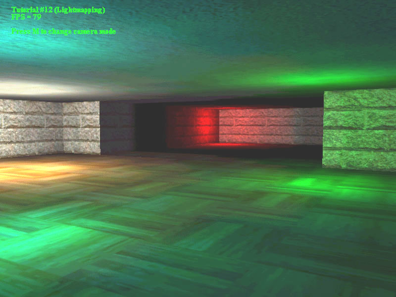
光照貼圖教程
http://www.alsprogrammingresource.com/lightmapping_tutorial.html
光照貼圖教程
作者:Alan Baylis 19/12/2001

在大多數遊戲中,光照貼圖仍然是首選的照明方法,也就是因為無論場景中有多少燈光,它都是快速的,如果你曾經拍過一個沒有破裂或者沒有破壞的燈泡而是周圍的燈光然後,你已經看到了行動(或缺乏)的光照貼圖。它們不適合動態照明,但可以應用光照貼圖主題的輕微變化來產生假動態光,例如開/關或閃爍的燈光(通常使用多個光照貼圖)。
光照貼圖基本上只是包含亮度資訊而不是影象的紋理。光照貼圖的元素稱為亮度,因為它們代表光度的元素。生成光照貼圖後,應用於多邊形時,要點亮的紋理和光照貼圖會混合在一起,以產生最終效果。可以在執行之前預先計算混合以加速程式,儘管現在的趨勢是使用硬體多紋理。
光照貼圖對於任何遊戲引擎來說幾乎都是必不可少的,但我發現這個主題缺乏教程或明確的來源,所以提供本教程和演示來填補一些空白。這是我建立光照貼圖的第一次嘗試,因此可能存在錯誤的來源或其他方式。
在開始之前,請注意示例程式碼與OpenGL API相容,並且只處理三角形(我仍然將它們稱為多邊形。)
第一步是計算光照貼圖的UV座標。在某些情況下,您可以使用紋理的UV座標,但這並不適用於所有情況,因此為此,我們使用稱為平面對映的過程。簡而言之,這意味著我們將多邊形的座標投影到主軸平面上,然後將新座標轉換為2D紋理空間,為我們留下0到1之間的正交UV座標。
要將多邊形的座標投影到主軸平面上,我們必須首先確定要使用的三個平面中的哪一個。這是通過檢查多邊形法線的哪個分量最大(使用絕對值),如果x分量最大,我們對映到YZ平面,如果y分量最大,我們對映到XZ平面,或者如果z分量是我們對映到XY平面上的最大值。現在我們知道要對映到哪個平面,我們通過使用每個頂點的兩個相關元件並丟棄第三個,將多邊形的座標投影到平面上。換句話說,如果我們對映到YZ平面,我們使用每個多邊形頂點的y和z分量並刪除x分量。
在此示例程式碼中,假設我們為具有三個頂點的單個多邊形制作光照貼圖,並且具有每個頂點具有UV座標的光照貼圖結構。我還設定了一個標誌,指示我們要對映到哪個平面,稍後將使用該平面。
        poly_normal = polygon.GetNormal();

        poly_normal.Normalize();


        if(fabs(poly_normal.x)> fabs(poly_normal.y)&&

            fabs(poly_normal.x)> fabs(poly_normal.z))

        {

            flag = 1;

            lightmap.Vertex [0] .u = polygon.Vertex [0] .y;

            lightmap.Vertex [0] .v = polygon.Vertex [0] .z;

            lightmap.Vertex [1] .u = polygon.Vertex [1] .y;

            lightmap.Vertex [1] .v = polygon.Vertex [1] .z;

            lightmap.Vertex [2] .u = polygon.Vertex [2] .y;

            lightmap.Vertex [2] .v = polygon.Vertex [2] .z;

        }

        否則if(fabs(poly_normal.y)> fabs(poly_normal.x)&&

                 fabs(poly_normal.y)> fabs(poly_normal.z))

        {

            flag = 2;

            lightmap.Vertex [0] .u = polygon.Vertex [0] .x;

            lightmap.Vertex [0] .v = polygon.Vertex [0] .z;

            lightmap.Vertex [1] .u = polygon.Vertex [1] .x;

            lightmap.Vertex [1] .v = polygon.Vertex [1] .z;

            lightmap.Vertex [2] .u = polygon.Vertex [2] .x;

            lightmap.Vertex [2] .v = polygon.Vertex [2] .z;

        }

        其他

        {

            flag = 3;

            lightmap.Vertex [0] .u = polygon.Vertex [0] .x;

            lightmap.Vertex [0] .v = polygon.Vertex [0] .y;

            lightmap.Vertex [1] .u = polygon.Vertex [1] .x;

            lightmap.Vertex [1] .v = polygon.Vertex [1] .y;

            lightmap.Vertex [2] .u = polygon.Vertex [2] .x;

            lightmap.Vertex [2] .v = polygon.Vertex [2] .y;

        }
然後,我們將這些光照貼圖UV座標轉換為2D紋理空間。要做到這一點,我們必須首先找到這些座標的邊界框(通過使用
最小值和最大值)並找出這些最小值和最大值之間的差值(delta)。完成此操作後,我們可以通過從UV座標中減去最小UV值然後除以delta值來縮放相對於原點的所有光照貼圖的UV座標。
        Min_U = lightmap.Vertex [0] .u;

        Min_V = lightmap.Vertex [0] .v;

        Max_U = lightmap.Vertex [0] .u;

        Max_V = lightmap.Vertex [0] .v;


        for(int i = 0; i <3; i ++)

        {

            if(lightmap.Vertex [i] .u <Min_U)

                Min_U = lightmap.Vertex [i] .u;

            if(lightmap.Vertex [i] .v <Min_V)

                Min_V = lightmap.Vertex [i] .v;

            if(lightmap.Vertex [i] .u> Max_U)

                Max_U = lightmap.Vertex [i] .u;

        if(lightmap.Vertex [i] .v> Max_V)

                Max_V = lightmap.Vertex [i] .v;

        }


        Delta_U = Max_U  -  Min_U;

        Delta_V = Max_V  -  Min_V;


        for(int i = 0; i <3; i ++)

        {

            lightmap.Vertex [i] .u  -  = Min_U;

            lightmap.Vertex [i] .v  -  = Min_V;

            lightmap.Vertex [i] .u / = Delta_U;

            lightmap.Vertex [i] .v / = Delta_V;

        }
所以現在我們可以使用光照貼圖UV座標來計算lumels。我們需要使用兩個邊進行插值,我們可以使用我們計算的最小和最大UV座標來製作這些邊,但是使用平面方程Ax + By + Cz + D = 0將它們投影回多邊形平面。
距離=  - (poly_normal.x * pointonplane.x + poly_normal.y

                      * pointonplane.y + poly_normal.z * pointonplane.z);


    開關(旗幟)

        {

            案例1:// YZ飛機

                X =  - (poly_normal.y * Min_U + poly_normal.z * Min_V + Distance)

                        / poly_normal.x;

                UVVector.x = X;

                UVVector.y = Min_U;

                UVVector.z = Min_V;

                X =  - (poly_normal.y * Max_U + poly_normal.z * Min_V + Distance)

                        / poly_normal.x;

                Vect1.x = X;

                Vect1.y = Max_U;

                Vect1.z = Min_V;

                X =  - (poly_normal.y * Min_U + poly_normal.z * Max_V + Distance)

                        / poly_normal.x;

                Vect2.x = X;

                Vect2.y = Min_U;

                Vect2.z = Max_V;

            打破;


            案例2:// XZ Plane

                Y =  - (poly_normal.x * Min_U + poly_normal.z * Min_V + Distance)

                        / poly_normal.y;

                UVVector.x = Min_U;

                UVVector.y = Y;

                UVVector.z = Min_V;

                Y =  - (poly_normal.x * Max_U + poly_normal.z * Min_V + Distance)

                        / poly_normal.y;

                Vect1.x = Max_U;

                Vect1.y = Y;

                Vect1.z = Min_V;

                Y =  - (poly_normal.x * Min_U + poly_normal.z * Max_V + Distance)

                        / poly_normal.y;

                Vect2.x = Min_U;

                Vect2.y = Y;

                Vect2.z = Max_V;

            打破;


            情況3:// XY平面

                Z =  - (poly_normal.x * Min_U + poly_normal.y * Min_V + Distance)

                        / poly_normal.z;

                UVVector.x = Min_U;

                UVVector.y = Min_V;

                UVVector.z = Z;

                Z =  - (poly_normal.x * Max_U + poly_normal.y * Min_V + Distance)

                        / poly_normal.z;

                Vect1.x = Max_U;

                Vect1.y = Min_V;

                Vect1.z = Z;

                Z =  - (poly_normal.x * Min_U + poly_normal.y * Max_V + Distance)

                        / poly_normal.z;

                Vect2.x = Min_U;

                Vect2.y = Max_V;

                Vect2.z = Z;

            打破;

        }


        edge1.x = Vect1.x  -  UVVector.x;

        edge1.y = Vect1.y  -  UVVector.y;

        edge1.z = Vect1.z  -  UVVector.z;

        edge2.x = Vect2.x  -  UVVector.x;

        edge2.y = Vect2.y  -  UVVector.y;

        edge2.z = Vect2.z  -  UVVector.z;
現在我們有兩個邊向量,我們可以通過使用光照貼圖的寬度和高度沿這些邊插值來找到世界空間中的lumel位置。我用來計算每個lumel顏色的方法是通過反覆試驗找到的,但基本上使用Lambert公式來縮放RGB強度,我很快就能找到關於這個主題的一些資訊,它會得到改進。我還檢查了燈光所在的多邊形的哪一側,以便只有前面的多邊形被點亮。
  for(int iX = 0; iX <Width; iX ++)

        {

            for(int iY = 0; iY <Height; iY ++)

            {

                ufactor =(iX /(GLfloat)Width);

                vfactor =(iY /(GLfloat)高度);

                newedge1.x = edge1.x * ufactor;

                newedge1.y = edge1.y * ufactor;

                newedge1.z = edge1.z * ufactor;

                newedge2.x = edge2.x * vfactor;

                newedge2.y = edge2.y * vfactor;

                newedge2.z = edge2.z * vfactor;


                lumels [iX] [iY] .x = UVVector.x + newedge2.x + newedge1.x;

                lumels [iX] [iY] .y = UVVector.y + newedge2.y + newedge1.y;

                lumels [iX] [iY] .z = UVVector.z + newedge2.z + newedge1.z;


                combinedred = 0.0;

                combinedgreen = 0.0;

                combinedblue = 0.0;

                for(int i = 0; i <numStaticLights; i ++)

                {

                    if(ClassifyPoint(staticlight [i] .Position,

                        pointonplane,poly_normal)== 1)

                    {

                      lightvector.x = staticlight [i] .Position.x  -  lumels [iX] [iY] .x;

                      lightvector.y = staticlight [i] .Position.y  -  lumels [iX] [iY] .y;

                      lightvector.z = staticlight [i] .Position.z  -  lumels [iX] [iY] .z;

                      lightdistance = lightvector.GetMagnitude();

                      lightvector.Normalize();

                        cosAngle = DotProduct(poly_normal,lightvector);

                        if(lightdistance <staticlight [i] .Radius)

                        {

                            intensity =(staticlight [i] .Brightness * cosAngle)

                                          / lightdistance;

                            combinedred + = staticlight [i] .Red * intensity;

                            combinedgreen + = staticlight [i] .Green * intensity;

                            combinedblue + = staticlight [i] .Blue * intensity;

                        }

                    }

                }

                if(combinedred> 255.0)

                    combinedred = 255.0;

                if(combinedgreen> 255.0)

                    combinedgreen = 255.0;

                if(combinedblue> 255.0)

                    combinedblue = 255.0;

                lumelcolor [iX] [iY] [0] = combinedred;

                lumelcolor [iX] [iY] [1] = combinedgreen;

                lumelcolor [iX] [iY] [2] = combinedblue;

            }

        }
下一部分採用lumelcolor陣列並將其放入RGBA格式,適合儲存為首選影象型別。
        for(int iX = 0; iX <(Width * 4); iX + = 4)

        {

            for(int iY = 0; iY <Height; iY + = 1)

            {

              lightmap [iX + iY * Height * 4] =(char)lumelcolor [iX / 4] [iY] [0];

              光照貼圖[iX + iY *高度* 4 + 1] =(字元)lumelcolor [iX / 4] [iY] [1];

              光照貼圖[iX + iY *高度* 4 + 2] =(字元)lumelcolor [iX / 4] [iY] [2];

              光照貼圖[iX + iY *高度* 4 + 3] = 255;

            }

        }
最後,需要注意的一些事項是:
靜態燈包含紅色,綠色和藍色值,範圍為0-255以及亮度和半徑值。平衡亮度和半徑是一項手動任務,可以產生不同的效果; 根據您想要的光效實驗這些。
與直覺相反,較小的光照貼圖可以產生更好的效果。如果光照貼圖太大,您將得到非常明顯的光環而不是光滑的混合。16x16大小的光照貼圖似乎確實是最佳尺寸
當兩個不同大小的多邊形從一個邊緣到另一個邊緣放置,並且兩個光線都照射在它們上面時,邊緣的任何一側的光值都不符合我們的要求。我很確定這是因為光照貼圖對每個多邊形的縮放比例不同,當光照貼圖較大並且有更多的取樣點時它不是問題(但是我們遇到上述光環問題)。要使觸控的多邊形具有相同的邊長,但這將是乏味的。我仍在努力解決這個問題,並希望對此問題有任何想法
參考文獻:
