
Arduino 和 TB6612FNG 驅動直流電機
TB6612FNG 電機驅動模組
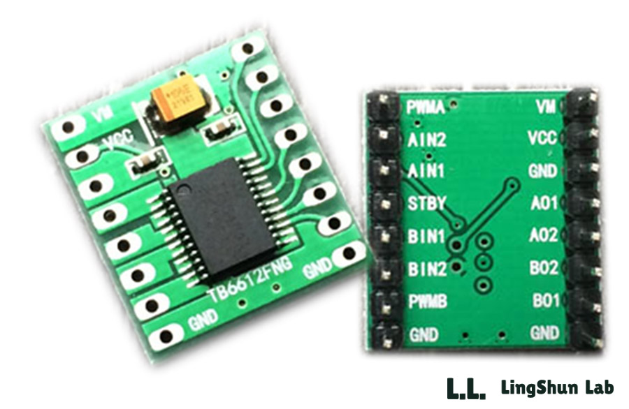
該模組相對於傳統的L298N效率上提高很多,體積上也大幅度減少,在額定範圍內,晶片基本不發熱。
TB6612FNG每通道輸出最高1.2 A的連續驅動電流,啟動峰值電流達2A/3.2 A(連續脈衝/單脈衝);
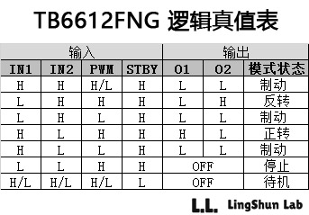
4種電機控制模式:正轉/反轉/制動/停止;
PWM支援頻率高達100 kHz;
待機狀態;
片內低壓檢測電路與熱停機保護電路;
工作溫度:-20~85℃;
SSOP24小型貼片封裝。
本篇文章參考任意門
引腳說明
A控制訊號輸入------PWMA VM ------電機驅動電壓輸入端(4.5V-15V)
A電機輸入端2 ------AIN2 VCC ------邏輯電平輸入端(2.7V-5.5V)
A電機輸入端1 ------AIN1 GND ------ 接地
正常工作/待機狀態控制端------STBY AO1 ------- A電機輸出端1
B電機輸入端1------BIN1 AO2 ------ A電機輸出端2
B電機輸入端2------BIN2 BO2 ------ B電機輸出端2
B控制訊號輸入端------PWMB BO1 ------ B電機輸出端1
接地------GND GND ------- 接地
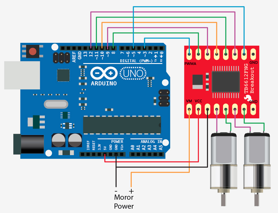
接線方式
程式實現
//motor A connected between A01 and A02
//motor B connected between B01 and B02

int STBY = 10; //standby

//Motor A
int PWMA = 3; //Speed control
int AIN1 = 9; //Direction
int AIN2 = 8; //Direction

//Motor B
int PWMB = 5; //Speed control
int BIN1 = 11; //Direction
int BIN2 = 12; //Direction

void setup(){
  pinMode(STBY, OUTPUT);

  pinMode(PWMA, OUTPUT);
  pinMode(AIN1, OUTPUT);
  pinMode(AIN2, OUTPUT);

  pinMode(PWMB, OUTPUT);
  pinMode(BIN1, OUTPUT);
  pinMode(BIN2, OUTPUT);
}

void loop(){
  move(1, 255, 1); //motor 1, full speed, left
  move(2, 255, 1); //motor 2, full speed, left

  delay(1000); //go for 1 second
  stop(); //stop
  delay(250); //hold for 250ms until move again

  move(1, 128, 0); //motor 1, half speed, right
  move(2, 128, 0); //motor 2, half speed, right

  delay(1000);
  stop();
  delay(250);
}


void move(int motor, int speed, int direction){
//Move specific motor at speed and direction
//motor: 0 for B 1 for A
//speed: 0 is off, and 255 is full speed
//direction: 0 clockwise, 1 counter-clockwise

  digitalWrite(STBY, HIGH); //disable standby

  boolean inPin1 = LOW;
  boolean inPin2 = HIGH;

  if(direction == 1){
    inPin1 = HIGH;
    inPin2 = LOW;
  }

  if(motor == 1){
    digitalWrite(AIN1, inPin1);
    digitalWrite(AIN2, inPin2);
    analogWrite(PWMA, speed);
  }else{
    digitalWrite(BIN1, inPin1);
    digitalWrite(BIN2, inPin2);
    analogWrite(PWMB, speed);
  }
}

void stop(){
//enable standby
  digitalWrite(STBY, LOW);
}
例項效果
通電,並測量馬達A與B的輸出電壓,基本相同,電壓差在正負0.03V,輸出穩定。
想必能完美解決L9110S 和 L298N兩路電機輸出電壓誤差大導致的走不到直線。