
kinect v2 標定
Kinect2 Calibration
Maintainer
Note: Please use the GitHub issues for questions and problems regarding the iai_kinect2 package and its components. Do not write emails.
Description
This tool uses OpenCV to calibrate two cameras to each other. It is specially designed for the Kinect One. It uses chess or circle boards.
Dependencies
- ROS Hydro/Indigo
- OpenCV
for the ROS packages look at the package.xml
Usage
kinect2_calibration [options]
  name: 'any string' equals to the kinect2_bridge topic base name
  mode: 'record' or 'calibrate'
  source: 'color', 'ir', 'sync', 'depth'
  board:
    'circle<WIDTH>x<HEIGHT>x<SIZE>'  for symmetric circle grid
    'acircle<WIDTH>x<HEIGHT>x<SIZE>' for asymmetric circle grid
    'chess<WIDTH>x<HEIGHT>x<SIZE>'   for chessboard pattern
  distortion model: 'rational' for using model with 8 instead of 5 coefficients
  output path: '-path <PATH>'
Key bindings
Windows:
ESC,q: QuitSPACE,s: Save the current image for calibrationl: decrease min and max value for IR value rageh: increase min and max value for IR value rage1: decrease min value for IR value rage2: increase min value for IR value rage3: decrease max value for IR value rage4: increase max value for IR value rage
Terminal:
CRTL+c: Quit
Calibration patterns
Any chessboard pattern or symmetric or asymmetric circle grid should work. Three different chessboard patterns are located inside the
kinect2_calibration/patterns folder:
Other patterns are available at OpenCV:
The standard board is a 7x6 0.108m chessboard from the PR2. But any other board can be specified with as parameter. For example a circle board with 8x7 circles in 0.02m distance between them
rosrun kinect2_calibration kinect2_calibration record color circle8x7x0.02.
Recently, to calibrate our sensors, we have used the chess5x7x0.03 pattern, as it can be printed easily on a good laser printer on A4 paper.
Calibrating the Kinect One
Recommended preparation:
- Print your calibration pattern (for the examples, we used chess5x7x0.03) and glue it to a flat object. It is very important that the calibration pattern is very flat. Also, check with a caliper that the distance between the features of the printed pattern is correct. Sometimes printers scale the document, and the calibration won't work. For the mentioned pattern, the distance between intersections of black and white corners should be 3cm exactly.
- Get two tripods, one for holding the calibration pattern, and another one for holding the kinect2 sensor. Ideally, the tripod for the kinect2 will have a ball head, to allow you to move it easily and lock it in place before you take an image. It is very important that the sensor is stable (and the image is clear and not blurred) before you take an image. The tripod will specially help you to make sure that the sensor has not moved between the moment the IR and the RGB images are taken.
- When recording images for all the steps indicated below (RGB, IR, SYNC), start the recording program, then press spacebar to record each image. The calibration pattern should be detected (indicated by color lines overlayed on the calibration pattern), and the image should be clear and stable.
- It is recommended to take images that show the calibration pattern in all areas of the image, and with different orientations of the pattern (tilting the pattern relative to the plane of the image), and at least two distances. So you can easily reach 100 images per calibration set.
- We normally start at a short distance, where the calibration pattern covers most of the image, there we take several pictures tilting the calibration pattern vertically, then horizontally. Imagine a ray coming out of the camera sensor, this makes sure that you have images where the calibration pattern is not perpendicular to that ray.
- Then we move the calibration pattern further away, and for different orientations (tilting) of the pattern, we take many images so that we calibration pattern is present around most of the camera image. For example, at first the calibration pattern is on the left upper corner. Then on the next image on the upper middle, then on the upper right corner. Then some images where the calibration pattern is in the middle vertically, etc...
Typical calibration setup
Detailed steps:
- If you haven't already, start the kinect2_bridge with a low number of frames per second (to make it easy on your CPU):
rosrun kinect2_bridge kinect2_bridge _fps_limit:=2 - create a directory for your calibration data files, for example:
mkdir ~/kinect_cal_data; cd ~/kinect_cal_data - Record images for the color camera:
rosrun kinect2_calibration kinect2_calibration chess5x7x0.03 record color - Calibrate the intrinsics:
rosrun kinect2_calibration kinect2_calibration chess5x7x0.03 calibrate color - Record images for the ir camera:
rosrun kinect2_calibration kinect2_calibration chess5x7x0.03 record ir - Calibrate the intrinsics of the ir camera:
rosrun kinect2_calibration kinect2_calibration chess5x7x0.03 calibrate ir - Record images on both cameras synchronized:
rosrun kinect2_calibration kinect2_calibration chess5x7x0.03 record sync - Calibrate the extrinsics:
rosrun kinect2_calibration kinect2_calibration chess5x7x0.03 calibrate sync - Calibrate the depth measurements:
rosrun kinect2_calibration kinect2_calibration chess5x7x0.03 calibrate depth - Find out the serial number of your kinect2 by looking at the first lines printed out by the kinect2_bridge. The line looks like this:
device serial: 012526541941 - Create the calibration results directory in kinect2_bridge/data/$serial:
roscd kinect2_bridge/data; mkdir 012526541941 - Copy the following files from your calibration directory (~/kinect_cal_data) into the directory you just created:
calib_color.yaml calib_depth.yaml calib_ir.yaml calib_pose.yaml - Restart the kinect2_bridge and be amazed at the better data.
Calibration of the depth measurements
I did some tests on the measured and the computed distance based on the detected chess board. It seems like the Kinect2 (or at least the Kinect2s I am using) has a static offset of around 24 mm. As shown in the following images, one can see, that the difference between measured and computed distance is unrelated to the x and y coordinates of the pixel and also unrelated to the distance.
For the images above ~400 images of a 4x5x0.03 chessboard in different orientations, distances and image positions were used. The code for computing the depth offset is added to the calibration tool.
GNUPlot
The depth calibration creates a file named plot.dat inside the calibration folder. This files contains the results of the calibration in 5 columns: x, y, computed depth, measured depth, difference between computed and measured depth.
-
Difference between measured/computed distance
set xlabel "Measured distance"set ylabel "Computed distance"plot 'plot.dat' using 3:4 with dots title "Difference between measured/computed distance"
- Difference relative to x coordinate
set xlabel "X"set ylabel "Distance difference"plot 'plot.dat' using 1:5 with dots title "Difference relative to X-coordinate"
- Difference relative to y coordinate
set xlabel "Y"set ylabel "Distance difference"plot 'plot.dat' using 2:5 with dots title "Difference relative to Y-coordinate"
- Difference relative to XY-coordinate
set xlabel "X"set ylabel "Y"set zlabel "Distance difference"splot 'plot.dat' using 1:2:5 with dots palette title "Difference relative to XY-coordinate"
## Example results
Example calibration results can be found in the directory [kinect2_bridge/data/](../kinect2_bridge/data).
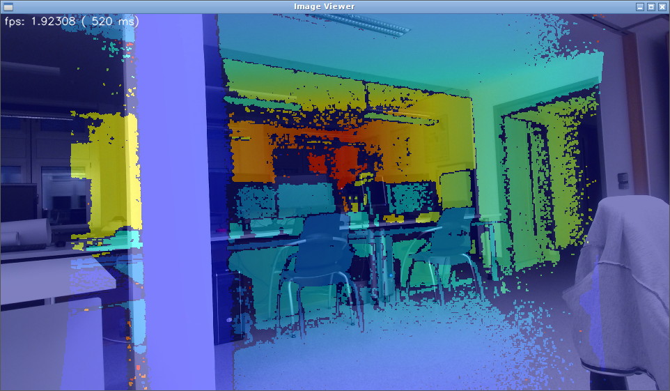
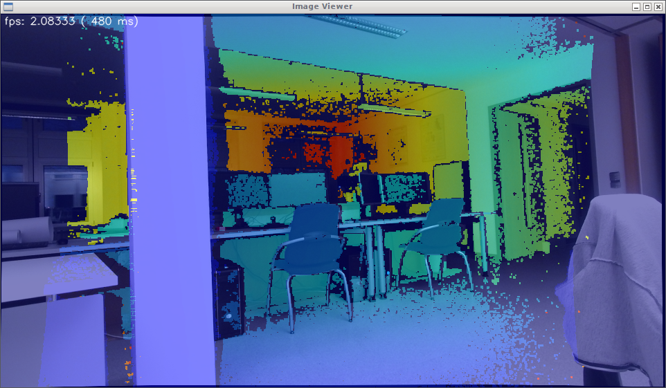
The following images were made before and after the calibration, using the kinect2 viewer.
- For the superimposed images: `rosrun kinect2_viewer kinect2_viewer hd image`
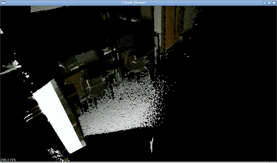
- For the point cloud images: `rosrun kinect2_viewer kinect2_viewer hd cloud`
- For the superimposed and point cloud images: `rosrun kinect2_viewer kinect2_viewer hd both`
raw here stands for raw data transmission aka uncompressed.
Uncalibrated rectified images (depth and RGB superimposed):
Calibrated rectified images (depth and RGB superimposed):
Uncalibrated depth cloud:
Calibrated depth cloud:
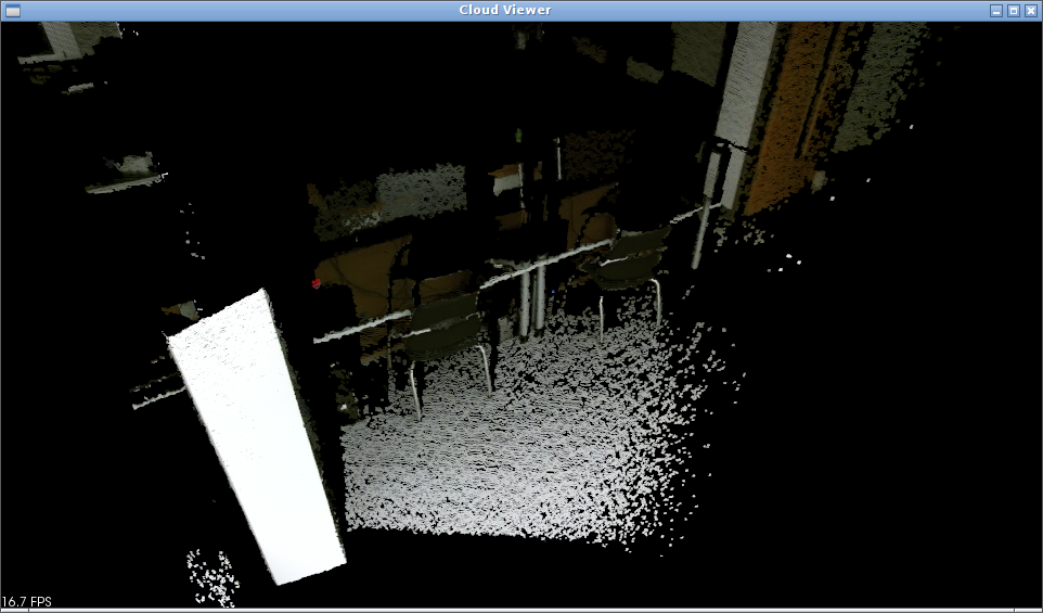
Note how the color is now correctly applied on the depth data. This is specially evident around strong edges, like the edge of the white column on the left.