利用GLSL繪製曲線
阿新 • • 發佈:2018-11-19
以前的專案裡,我曾經用qwt繪製曲線.qwt是一種基於qt的第三方外掛。用qwt繪製的好處是,在待繪製的樣本數較多時(〉=1000),仍然可以在很短的時間內完成繪製。本篇部落格介紹一種辦法,不再利用qwt,而是直接利用GLSL來實現高速繪製曲線。這個功能封裝在類GLCurve中。
標頭檔案:
#pragma once

#include <QOpenGLWidget>
#include <QOpenGLFunctions>
#include <QOpenGLShader>
#include <QOpenGLShaderProgram>
#include <QTimer>

class GLCurve : public QOpenGLWidget, protected QOpenGLFunctions
{
    Q_OBJECT

public:
    GLCurve(QWidget *parent = 0);
    ~GLCurve();

    GLuint                          m_uiVertLoc;
    QOpenGLShaderProgram    *       m_pProgram;

    GLfloat                 *       m_pVertices;
    int                             m_iCount;//資料樣本數
    bool                            m_bVisibility;
    unsigned int                    m_uiColor;
    double                          m_dUpperBound;
    double                          m_dLowerBound;
    double                          m_dLeftBound;
    double                          m_dRightBound;

    void                            vSetXBounds(double, double);
    void                            vSetYBounds(double, double);
    void                            vSetVertices(unsigned char *, int);

protected:
    void        initializeGL();
    void        paintGL();
    void        resizeGL(int w, int h);
public slots:

};
cpp檔案:
#include "GLCurve.h"

GLCurve::GLCurve(QWidget *parent)
    : QOpenGLWidget(parent)
{
    m_bVisibility = true;
    m_uiColor = 0x000000;
    m_iCount = 0;

    m_pVertices = NULL;
    m_dUpperBound = 255;
    m_dLowerBound = 0;
}

GLCurve::~GLCurve()
{
    delete m_pProgram;

    if(m_pVertices)
    {
        delete [] m_pVertices;
    }
}

void GLCurve::initializeGL()
{
    initializeOpenGLFunctions();

    QOpenGLShader *vshader = new QOpenGLShader(QOpenGLShader::Vertex, this);
    const char *vsrc =
                        "#version 330\n"
                        "in vec3 pos;\n"
                        "uniform mat4 mat4MVP;\n"
                        "void main()\n"
                        "{\n"
                        "    gl_Position = mat4MVP * vec4(pos, 1.0);\n"
                        //紋理的Y方向是從下向上的,而pos.y的正方向是從上向下,所以是1.0 - pos.y / 180.0
                        "}\n";
    vshader->compileSourceCode(vsrc);

    QOpenGLShader *fshader = new QOpenGLShader(QOpenGLShader::Fragment, this);
    const char *fsrc =
                        "#version 330\n"
                        "out vec4 color;\n"
                        "void main()\n"
                        "{\n"
                        "    color = vec4(0,0,0,0);\n"//注意,texCoord的值域在0-1之間
                        "}\n";
    fshader->compileSourceCode(fsrc);

    m_pProgram = new QOpenGLShaderProgram;
    m_pProgram->addShader(vshader);
    m_pProgram->addShader(fshader);
    m_pProgram->link();
    m_pProgram->bind();

    m_uiVertLoc = m_pProgram->attributeLocation("pos");
    m_pProgram->enableAttributeArray(m_uiVertLoc);


    glEnable(GL_DEPTH_TEST);
    glClearColor(0.4,0.4,0.4,1);
}

void GLCurve::paintGL()
{
    //QMatrix4x4在宣告時被預設為單位矩陣
    QMatrix4x4 m1, m2, m3, m;

    double dYRange = m_dUpperBound - m_dLowerBound;
    double dYMid = (m_dUpperBound + m_dLowerBound) / 2;
    double dXRange = m_dRightBound - m_dLeftBound;
    double dXMid = (m_dLeftBound + m_dRightBound) / 2;

//註釋:
//    m1.ortho(-dXRange / 2 * 1.3, /*從攝像機開始,沿X軸負方向運動dXRange / 2 * 1.3的距離(世界座標),作為視景體的左邊界*/
//             dXRange / 2 * 1.3, /*從攝像機開始,沿X軸正方向運動 dXRange / 2 * 1.3的距離(世界座標),作為視景體的右邊界*/
//             0 - dYRange / 2 * 1.3, /*從攝像機開始,沿Y軸負方向運動dYRange / 2 * 1.3的距離(世界座標),作為視景體的下邊界*/
//             dYRange / 2 * 1.3, /*從攝像機開始,沿Y軸正方向運動dYRange / 2 * 1.3的距離(世界座標),作為視景體的上邊界*/
//             0.0f, /*從攝像機開始,沿Z軸正方向運動0距離(世界座標),作為視景體的前邊界*/
//             15.0f/*從攝像機開始,沿Z軸負方向運動15.0的距離(世界座標),作為視景體的後邊界*/);
    m1.ortho(-dXRange / 2 * 1.3, dXRange / 2 * 1.3, 0 - dYRange / 2 * 1.3, dYRange / 2 * 1.3, 0.0f, 15.0f);

    //註釋:
//    m2.lookAt(QVector3D(dXMid,dYMid,10)/*攝像機的世界座標*/, QVector3D(dXMid,dYMid,0)/*圖片中心的世界座標*/, QVector3D(0,10,0));
    m2.lookAt(QVector3D(dXMid,dYMid,10), QVector3D(dXMid,dYMid,0), QVector3D(0,10,0));

    m = m1 * m2 * m3;

    m_pProgram->setUniformValue("mat4MVP", m);
    glClear(GL_COLOR_BUFFER_BIT | GL_DEPTH_BUFFER_BIT);
    if(m_iCount >0)
    {
        m_pProgram->setAttributeArray(m_uiVertLoc, m_pVertices, 3, 0);
        glDrawArrays(GL_LINE_STRIP, 0, m_iCount);
    }
}

void GLCurve::resizeGL(int w, int h)
{
    glViewport(0, 0, w, h);
}

void GLCurve::vSetVertices(unsigned char * arrVertices, int iCount)
{
     m_iCount = iCount;
     m_pVertices = new GLfloat[iCount * 3];
     for(int k = 0; k < iCount; k++)
     {
         m_pVertices[3* k] = k;
         m_pVertices[3* k + 1] = arrVertices[k];
         m_pVertices[3 * k + 2] = 0;
     }
}

void GLCurve::vSetXBounds(double dLeftBound, double dRightBound)
{
    m_dLeftBound = dLeftBound;
    m_dRightBound = dRightBound;
}

void GLCurve::vSetYBounds(double dLowerBound, double dUpperBound)
{
    m_dUpperBound = dUpperBound;
    m_dLowerBound = dLowerBound;
}
呼叫時,要先設定橫向和縱向的表數範圍vSetX(Y)Bounds(),然後把原始資料通過vSetVertices()送入GLCurve類:
#include "GLCurve.h"
#include <QApplication>

int main(int argc, char *argv[])
{
    QApplication a(argc, argv);
    GLCurve w;

    int iLen  = 256;
    unsigned char * arr = new unsigned char[iLen];
    for(int k = 0; k < iLen; k++)
    {
        arr[k] = k;
    }

    w.vSetXBounds(0, iLen - 1);
    w.vSetYBounds(0, iLen - 1);
    w.vSetVertices(arr, iLen);
    w.show();

    return a.exec();
}
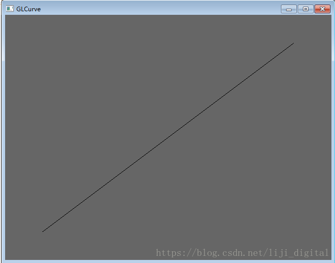
效果:
程式設計師可以進一步的在圖片上新增X軸和Y軸,方法參見:
https://blog.csdn.net/liji_digital/article/details/78473568
程式碼可以在我的資源下載https://download.csdn.net/download/liji_digital/10722512

