
ADAS/AD開發06
本文介紹下AD自動駕駛技術的“神器”- 高精地圖,也稱開了掛的“地圖感測器”。
一、有HD-Map之前的ADAS是如何實現車輛控制的?
在高精地圖加持之前的ADAS系統,功能一般是由感知+資料處理+系統狀態機+PID控制器(或LQR控制器)組成的。拿智慧前視攝像頭模組實現LKA功能為例,按照dataflow來梳理:
- 通過鏡頭和COMS影象感測器來獲取單幀圖片;
- 按照感興趣區域(ROI,region-of-interest)裁剪圖片;
- 圖片經過灰度化、二值化,獲得車道線的Lane_marklet(車道線標記小段,如圖1);
- 通過霍夫變換,將marklet擬合成Lane_segments(車道線段,如圖2);
- 將Lane_segments的位置從圖片座標系轉換為世界座標系;
- 對Lane_segments進行合併,合併不了的刪除掉;
- 從整車CAN上抓取vehicle speed、yawrate等訊號,用於計算三階車道線模型,獲得車道線的Lane_geometry。所謂的三階車道線模型,即Lateral Offset = a0 + a1*x + a2*x2+ a3*x3 ; 其中,x - longitudinal range x X向參考距離;該距離x=V(車速) * Tpreview(sec) , T 代表0.5-1秒之間的一個標定值。a0 - 當前Y向位置; a1 - Y向速度; a2 - 曲率;a3 - 曲率變化率。
- 通過卡爾曼濾波器,跟蹤並更新車道線的Lane_geometry(車道幾何線,用於抽象車道線,如圖3)的幾何形狀;
- 通過霍夫變換的信心值和車道線跟蹤器的信心值,獲得車道線的信心值;
- 將車道線資訊和來自車輛CAN上的其他資訊(車速、YawRate、steer angle等)傳給LKA功能;
- LKA對各種輸入訊號進行資料處理,例如濾波、判斷等;
- 計算可以直接被LKA狀態機使用的判斷訊號,如TTLC(time to lane crossing)、Lane position、車輪外緣到車道線的距離、Lane change、Road status(路面曲率等)、方向盤轉角的inhibit訊號、油門踏板的inhibit訊號、剎車踏板的inhibit訊號等等;
- LKA主狀態機進行LKA狀態控制,狀態包括:fault、off、standby、enabled、intervention left、intervention right、warning left、warning right等狀態,如圖6;
- 利用前饋PID控制器,通過引入主狀態機的狀態訊號,以及橫向速度、距離車道線橫向距離、heading angle、橫向加速度、路面曲率等引數,建立基於車輛運動狀態和路面狀態的前饋PID控制模型,計算轉向扭矩。
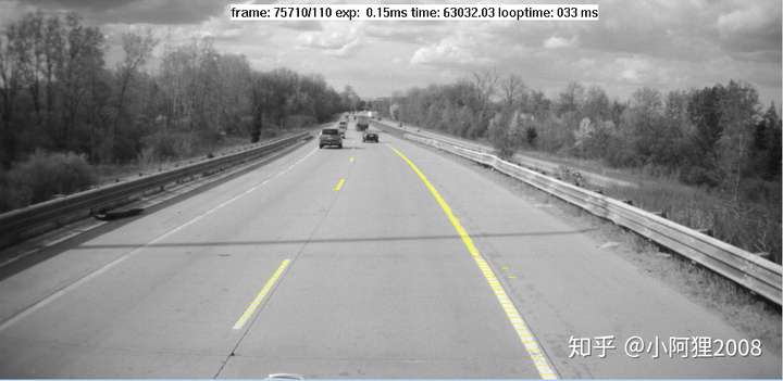
圖1 Lane Marklet 車道線標記小段,黃色
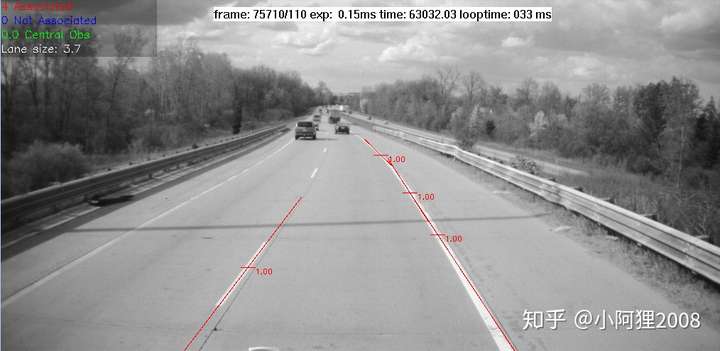
圖2 Lane Segments 車道線段,紅色
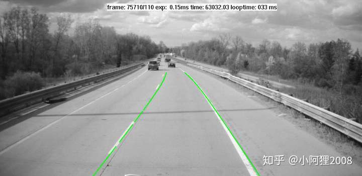
圖3 Lane Geometry 車道幾何線,綠色
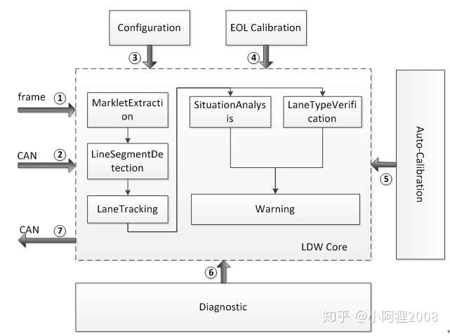
圖4 車道線檢測演算法框圖
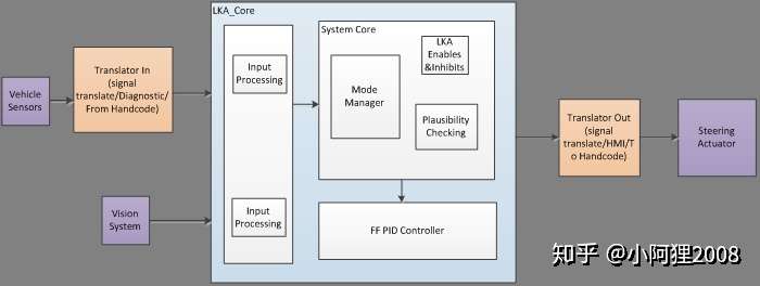
圖5 LKA功能架構
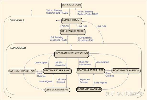
圖6 LKA主狀態機
通過上述描述,可以悉知,在ADAS功能中,根本沒有planning模組,車輛控制完全沒先驗軌跡(如圖7的綠色軌跡段)的存在,控制全靠計算車輛與兩個車道線之間的動態關係,利用PID控制器直接生成控制扭矩,來控制車輛的狀態。而AD領域的車輛控制,是有先驗軌跡的存在的,所有的精華都在先驗軌跡的生成,只要計算出先驗軌跡,車輛的真正控制非常簡單,例如按照先驗軌跡分解出車輛的速度-轉角控制量,然後速度再分解成加速度、減速度。加速度對應油門,減速度對應剎車,轉角對應方向盤轉角,車輛就可以按照先驗軌跡作為pilot,最大程度的擬合先驗軌跡行駛。這也就是所謂的ROS機器人技術路線(ROS,Robot Operating System 機器人作業系統)。這條“先驗軌跡”,其實就是像工廠裡的物料小車一樣,只不過工廠的物料小車是按照路面上事先貼好的磁性軌跡行駛的(如圖7),而智慧駕駛車的先驗軌跡是存在於planing演算法模組中的。

圖7 “先驗軌跡”trajectory
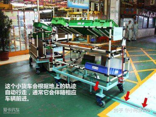
圖8 物料小車的磁性軌跡
而利用PID控制器這種粗暴的控制方式有很大的缺點。第一,演算法與功能落地(即在車上的匹配)之間,有個巨大的、技術邏輯上的“模糊地帶”,這個地帶沒有明顯的符合邏輯的方法可以幫助你順利的將演算法使用在目標車型上(例如無法通過準確的模擬來測試效果),只能靠工程實踐(也就是大量測試、標定、試引數)來縫合這個模糊地帶。這就是傳說中的“標定”!為什麼汽車行業有大量的標定工程師?例如,發動機標定工程師、安全氣囊控制器演算法標定工程師、ADAS feature標定工程師,就是因為功能在車輛上的“落地”應用,需要大量的功能標定工作,說白了就是各種試引數,例如湊PID引數,湊標定係數,有時候完全就是在硬標。第二,由於標定環節的存在,為了能夠更加準確的評判標定的效果和功能的效能(performance),只能設定更加複雜、巨大的測試驗證矩陣來cover住這種“稀裡糊塗”的功能匹配方式。
二、有了HD-Map之後的AD是如何進行車輛控制的?
首先,先貼出目前主流的高精地圖的資料格式,和包含的車道資訊。
typedef enum _GUIDETYPE
{
GUIDE_CAR_POS = 0, //車輛位置
GUIDE_LINE,
GUIDE_REGION,
GUIDE_OBJS,
GUIDE_MANEUVER,
GUIDE_MAX = 0xFFFFFFFF
} GUIDETYPE;
typedef struct _DiffPosition
{
int8 x; //經緯度^8後相對於上一個點的差值,第一個點儲存相對於指定位置的差值
int8 y;
int8 z;
int16 slope; //Value: [-9000,9000],Unit: 0.01 degree
int16 superelev; //如上
int16 heading; //Value: [0,36000],Unit: 0.01 degree, 北順
int16 curvature; //Value: [-10000,10000],Unit: 0.0001/m
//For example, 0.0123/m 表示為 Curvature =123
//- for right turn; + for left turn;
//Right or left is based on the link positive direction
} DiffPosition;
typedef struct _GuideLaneCenterline // 分段內的單條引導線,均為所屬分段的車道中心線
{
uint32 laneType; // 當前引導線所屬車道屬性
// bitmap, from right to left
// 1:Regular Lane
// 3:Acceleration Lane
// 4:Deceleration Lane
// 3 and 4: Compound lane
// 5:HOV Lane
// 7:Slow lane
// 8:Passing/Overtaking lane
// 9: Hard shoulder lane (no geometry) 10:Truck parking lane
// 11:Regulated access lane
// 17: Soft shoulder lane(no geometry)
// 18: Emergency parking strip(nogeometry)
// 19:Bus lane
// 20:Bicycle lane (no geometry) 21:Turn Lane
// 22:Reversible lane
// 23:Centre turn lane
// 24:Truck escape ramp
uint8 laneSeq; // lane sequence number of cur link,
// starts from 1 with the left most non-transition lane,
// and +1 each time from the left to right according to the travel direction
uint8 laneArrowType; // 當前引導線所屬車道上箭頭型別
// 0 Not applicable 沒有箭頭
// 1 Forward
// 2 Right
// 3 Right and forward
// 4 Left
// 5 Left and forward
uint8 lMarkingType; // 當前引導線左邊marking型別
// 0 Not investigated 10 Single Dashed
// 12 Short Thick Dashed
// 13 Double Dashed
// 20 Single Solid
// 21 Double Solid
// 30 Left Solid/Right Dashed
// 31 Left Dashed/Right Solid
// 32 Turn variable lane marking
// 33 Single thick solid
// 99 Virtual Marking
uint8 rMarkingType; // 同上
uint16 swidth; // cm,車道開始位置車道寬度
uint16 ewidth; // cm,車道結束位置車道寬度,若當前車道寬度沒有變化swidth,ewidth相等
// note:: 車道開始和結束位置寬度並非線性漸變
uint16 speedMax; // 速度單位:0.01m/s
uint16 speedMin; // 速度單位:0.01m/s
int64 x; //當前引導線起始點座標(GAUSS 單位 cm)
int64 y;
int32 z;
int16 posNum; //當前引導單元中的position點個數(每個點的座標儲存和前一個點的差值)(包含起始點,其xyz差值為0)
DiffPosition[posNum]; //當前引導線單元的差值position點的資訊(相對於前一個點的位置差值)
} GuideLaneCenterline;
typedef struct _GuidelinesSection //當前的引導線分段,包含>=1條引導線,分段內各個引導線按照GuidelineUnit儲存
{
int32 linkId; //當前分段id(2.0版本採用編譯後資料中的linkId),全球唯一,(*^__^*) ,和下面GUIDE_REGION中segId保持一致
int32 lenght; //當前路段長度,單位:cm
uint8 isBridge; // 0 is not bridge
uint8 isTunnel; // 0 is not tunnel
uint8 TranType; // Transition road type
// 0 means No transition zone
// 1 Lane(s) opening/closing on one side- i.e. Exit, Entrance
// 2 Lane(s) opening/closing in the middle– i.e. road split, road merge
// 3 Only for Toll Booth area. Toll booth entrance and toll booth exit are both transition road.
// For this section of road, Lane number or Lane Width is not applicable
// 4 Road width widening or narrowing or no change, but all lanes change simultaneously.
uint16 roadForm; // 0 Not attributed
// 1 JCT(Motorway Junction)
// 21 Entrance Ramp
// 22 Exit Ramp
int16 lineNum; //當前分段包含引導線總數,>=1,引導線按照從左到右順序依次儲存
uint16 topoSuccessor[lineNum]; //當前分段中各個引導線和下一個分段的拓撲連線關係,現在認為連線處為自然平滑連線關係
//採用bitmap方式。最低位表示最左車道是否存在脫出關係
//如當前分段中最左側車道(左1)和下一個分段左1、左2拓撲相連
//則successor二進位制表示為00000000 00000011
//當只存在一條引導線的時候successor二進位制表示為00000000 00000001
uint16 topoPredecessor[lineNum];//當前分段中各個引導線和上一個分段的拓撲連線關係,其他同上
GuideLaneCenterline[lineNum]; //當前分段的單條引導線儲存陣列,引導線Index從0開始遞增至lineNum-1
} GuidelinesSection;
typedef struct _Guidelines // **引導線總結構體**
{
uint8 sectionNum; //當前輸出引導線分段總數,各個分段按照脫出順序從自車位置開始向前依次儲存
GuidelinesSection subSectionLines[sectionNum]; //分段引導線資訊
} Guidelines;
typedef struct _RouteMarking
{
int8 lLaneSeq; // left lane sequence number of cur marking,
// starts from 1 with the left most non-transition lane,
// and +1 each time from the left to right according to the travel direction
// if not left lane, this param equal 0
int8 rLaneSeq; // right lane sequence number of cur marking
uint8 color; // 0 not know now
// 1 Others
// 2 White
// 3 Yellow
// 4 Left yellow/right white
// 5 Left white/right yellow
uint8 type; // 0 Not investigated 10 Single Dashed
// 12 Short Thick Dashed
// 13 Double Dashed
// 20 Single Solid
// 21 Double Solid
// 30 Left Solid/Right Dashed
// 31 Left Dashed/Right Solid
// 32 Turn variable lane marking
// 33 Single thick solid
// 99 Virtual Marking
uint8 width; // unit: cm
uint8 material; // 0 means Not applicable. If MarkType==99, this value is 99.
// 1 Painted
// 2 Raised pavement marker
// 3 Painted and Raised pavement marker
uint8 RDMarking; // 0 means Not applicable, means that this lane marking has no rhombus deceleration marking
// 1 This lane marking has rhombus deceleration marking on right side along the driving direction
// 2 This lane marking has rhombus deceleration marking on left side along the driving direction
// 3 This lane marking has rhombus deceleration marking on both sides along the driving direction
uint16 ptNum; // marking線上幾何點個數
Point16 pts[ptNum]; // 第一個點為相對於當前分段起始點的GAUSS座標差值 cm
// 隨後點為相對於前一個點的GAUSS座標差值 cm
} RouteMarking;
typedef struct _RouteSection
{
int32 linkId; // 當前分段id,全球唯一,(*^__^*) ,和上面GUIDE_LINE中segId保持一致
uint32 length; // 當前路段長度 單位:cm
Point32 pos; //當前分段起點相對於自車的位置座標(**自車座標系**下座標) cm
//一般為當前分段左邊第一條車道中心線沿行駛方向第一個點座標
//當車道為單向行駛車道時第一個點為車道s點
//當車道為雙向可行駛車道時,為到自車沿路線距離最近方向點
uint16 markingNum; // 一般一條車道左右兩邊兩條marking,但存在沒有marking線的車道,這個值可以為0
RouteMarking markings[markingNum];// as above
} RouteSection;
typedef struct _GuideSectionTopo // 前後兩條分段之間的拓撲連結關係
{
int16 inSegIdx; // 脫入分段在GuideRegion結構體中儲存陣列中的Index
int16 outSegIdx; // 脫出分段在GuideRegion結構體中儲存陣列中的Index
int16 inSegLaneNum; // 脫入分段上車道數
int16 outSegLaneNum; // 脫出分段上車道數
uint16 successorLane[inSegLaneNum]; // 脫入分段各個lane對應脫出分段上的連線的lane在其數字中的index
uint16 segType; // guide segment型別資訊
// 0: 表示當前自車車後沿路線上的分段
// 1: 表示當前自車車前沿路線上的分段
// 2: 表示當前自車前方第一個匯入點上其他非沿路線匯入分段
// 3: 表示當前自車前方第一個分叉點上其他非沿路線脫出分段
} GuideSectionTopo;
typedef struct _GuideRegion
{
int16 sectionNum; //當前REGION中的分段個數
int32 dsitance[sectionNum]; //各個分段起始位置到當前自車位置沿link線距離,單位cm
RouteSection routeSection[sectionNum]; //儲存分段資訊
int16 topoNum; // 前後兩條分段之間的拓撲連結關係個數
GuideSectionTopo topos[topoNum]; // 前後兩條分段之間的拓撲連結關係內容
} GuideRegion;
typedef enum _ADManeuverType
{
ADMT_none = 0,
ADMT_tollStation, //收費站
ADMT_serviceArea, //服務區
ADMT_notAllowOvertaking, //禁止超車
ADMT_allowOvertaking, //允許超車
ADMT_waypoints, //途經點
ADMT_endpoints, //終點
ADMT_enterRamp, //進入匝道
ADMT_leaveRamp, //駛離匝道
ADMT_rampImport, //岔口交匯
ADMT_overpass, //立交橋
ADMT_accelerationLane, //加速車道
ADMT_decelerationLane, //減速車道
ADMT_enterMainRoad, //進入主路
ADMT_distanceAlongRoadTips, //沿路行駛距離提示
ADMT_urgencyParkingStrip, //緊急停車帶
ADMT_tunnelEntrance, //隧道入口
ADMT_tunnelExport, //隧道出口
ADMT_leftNarrowed, //左側變窄
ADMT_rightNarrowed, //右側變窄
ADMT_bothSidesNarrowed, //兩側變窄
ADMT_narrowBridge, //窄橋
//todo 程式碼中出現JCT,但是在這裡沒有出現
ADMT_ComplexIntersection //複合路口
} ADManeuverType;
union ADManeuverUnionAttribute
{
uint8 nServiceDistance; // 當前maneuver為服務區的時候同時給出下一個服務區距離 km, 無效值-1,型別為ManeuverType_serviceArea時有效
uint8 wayPtNumber; // 當前到達的是第幾個途經點,型別為ManeuverType_waypoints時有效,無效值-1
uint8 rampType; // 當前匝道型別為上匝道還是下匝道或者是JCT,型別為ManeuverType_enterRamp時有效
//todo rampType和上面型別中的ADMT_enterRamp等區分清楚
// 0:下匝道 1:上匝道 2:JCT 255:無效值
uint8 importLaneSide; // 當前自車所在道路哪邊有車道匯入,型別為ManeuverType_rampImport時有效
// 0: 當前自車所在車道左側有匯入車道 1: 右側 2:左右都有 255:無效值
}
// 只包含lane id的link結構,用於表述maneuver上的lanetopo關係
struct LanePath
{
uint32_t laneNum;
LaneID* pathResult;
};
typedef struct _ADManeuver
{
ManeuverType maneuverType; //
int distance; // maneuver點到當前自車距離, cm
Point64 pos; // maneuver起始點絕對座標
int64 predecessorLinkId; // maneuver託入link id
int speed; // maneuver點之後的建議車速 0.01m/s
// ManeuverType_enterRamp ManeuverType_tunnelEntrance ManeuverType_distanceAlongRoadTips 為當前特殊lane上的建議速度
// ManeuverType_leaveRamp ManeuverType_tunnelExport 為當前maneuver點之後的建議車速
// ManeuverType_accelerationLane ManeuverType_decelerationLane 為當前加減速車道終點處的最低目標車速
int length; // maneuver為特殊路段時,特殊路段長度 cm,無效值-1, 以下型別有效
// ManeuverType_accelerationLane ManeuverType_decelerationLane
// ManeuverType_urgencyParkingStrip ManeuverType_tunnelEntrance
// ManeuverType_overpass // 天橋在當前行駛路段上的投影長度
int overpassHeight; // ManeuverType_overpass 天橋距離當前路線所屬道路路面高度 cm 無效值 -1
uint8 laneNumber; // maneuver所在位置脫出todo:主路上車道總數
uint8 laneSeqNum; // maneuver所對應特殊車道在主路上的lane seqNum,對以下型別有效
// ManeuverType_accelerationLane ManeuverType_decelerationLane
// ManeuverType_enterMainRoad ManeuverType_urgencyParkingStrip
uint16 suggestLanes; // bitmap 當前自車位置建議車道
// 遇到ManeuverType_distanceAlongRoadTips ManeuverType_narrowRoad ADMT_enterRamp
// 等型別時候車輛便要開始為其做相應變道準備
ADManeuverUnionAttribute unionAttribute; //互斥屬性儲存在一個聯合體中
//todo todo todo
uint8_t lanePathNum; // 從自車位置到maneuver所有LanePath number
LanePath* paths; // 從自車到maneuver位置所有lane的topo 關係
} ADManeuver;
根據以上高精地圖的結構體可以看出,擁有如此豐富的地圖資訊,要進行車輛控制,簡直就像開了掛一樣啊。假如車輛能夠動態掌握自車前1公里和後0.5公里的高精地圖資訊的話(也有設定成前500米後200米的),完全可以站在“上帝視角”提前計算出預先需要行駛的軌跡,比如在車輛需要下高架橋的場景中,車輛自己會根據高精地圖資訊提前計算出一個先驗軌跡,可能會是這樣的:先按照本車道中心線行駛200米,然後向右換道;由於通過感知和預測,知道右側有一輛車,在前方50m的位置正以較低速度行駛,所以換到右側車道時,要在右側車道行駛50m後,繼續向右換道,換到駛離高架路的輔道上,然後在輔路上行駛600m,下高架路。
當然,以上純屬是為了解釋先驗軌跡的概念,進行了誇張描述。事實上,一般受限於感知感測器的能力(前向毫米波雷達探測距離約170-220米,64線威力登鐳射雷達探測距離100米左右),一般先驗軌跡的長度設定在200米左右就足夠了,因為即便設定的更長,由於障礙物檢測、跟蹤無法超過200米的距離,因此將軌跡規劃距離設定太長也沒有太大意義。
最後提一點,先驗軌跡的規劃,不僅只考慮車道資訊,也要考慮攝像頭、毫米波雷達、鐳射雷達等感測器感知到的車道線、交通標誌、車輛、行人、騎自行車的人等等障礙物資訊和道路資訊。障礙物資訊包括體積資訊、位置資訊、運動狀態資訊,和障礙物的軌跡預測資訊。綜合以上所有資訊,才能規劃出理想的、不會發生交通事故的 、不會違反道路法律法規的、安全的、舒適的先驗軌跡!
三、車機(中控大屏)的導航是如何與智慧駕駛的高精地圖進行互動的?
先介紹下導航地圖與高精地圖的區別。
導航地圖,英文縮寫SD-Map,儲存的是道路級別的資訊,注意英文名road level info;導航地圖的路徑規劃,叫做全域性路徑規劃,注意英文名Routing(路由);
高精地圖,應為縮寫HD-Map,儲存的是車道級別的資訊,注意英文名Lane level info;高精地圖的路徑規劃,叫做區域性路徑規劃,注意英文名Planning(規劃);
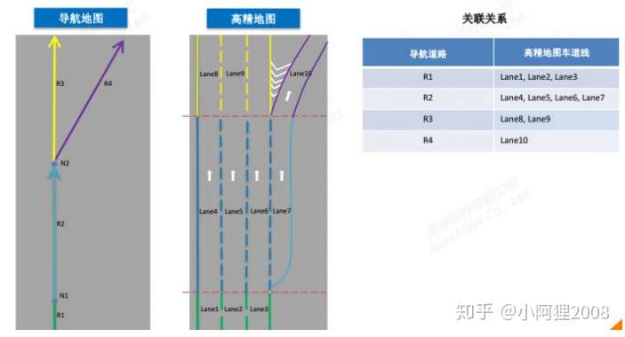
圖9 導航地圖與高精地圖的Mapping關係
如圖8所示,實際上,無論是SD-Map還是HD-Map,都有一個相同的概念(或者叫引數),就是Road Segments(也有叫做Road Section)的,本文稱作路段,路段的含義是:按照道路屬性是否發生變化將連續的道路分割成路段。所謂道路屬性發生了變化,例如車道線數量增加或減少了、右側一個車道分叉了(比如下高架路的輔道,存在道路分離點),如圖10所示。
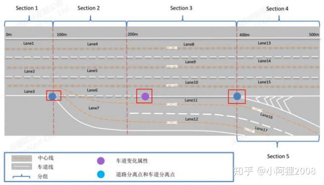
圖10 路段的定義
有了路段這個屬性,且路段屬性的唯一性。可以將SD-Map的路段與HD-Map的路段進行一對一的匹配。也就是說,當進行SD-Map的Routing規劃時,將整個routing的路段編號和資訊做成一個數組,傳送給HD-Map,HD-Map根據編號來依次提取road segments中的lane info,用於planning規劃,即先驗軌跡的規劃。