樹莓派 pcf8491 AD轉換模組使用
因為 專案需要因此要使用 PCF8491

1.準備工具
樹莓派pi一個。pcf8591一個。模擬量感測器一個(我這用 熱敏電阻當溫度計使用)。
2.原理。
PCF8591 是單片、單電源低功耗8位CMOS資料採集器件,具有4個模擬輸入、一個輸出和一個行I2C匯流排介面。
3個地址引腳A0、A1和A2用於程式設計硬體地址,允許將最多8個器件連線至I2C匯流排而不需要額外硬體。
器件的地址、控制和資料通過兩線雙向I2C匯流排傳輸。器件功能包括多路複用模擬輸入、片上跟蹤和保持功能、
8位模數轉換和8位數模擬轉換。最大轉換速率取決於I2C 匯流排的最高速率。
引腳定義:
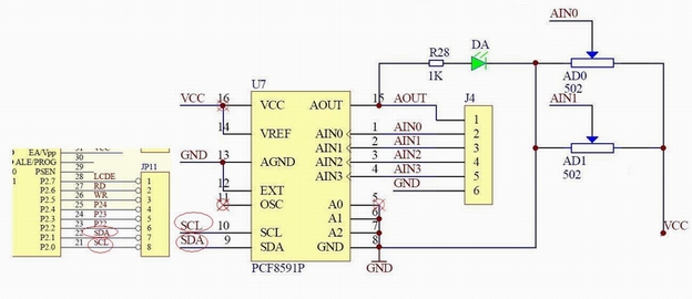
本模組左邊和右邊分別外擴2路排針介面,分別說明如下:
左邊 AOUT 晶片DA輸出介面
AINO 晶片模擬輸入介面0 我在使用的時候接的時A0,接的是光敏感測器的AO口;
AIN1 晶片模擬輸入介面1
AIN2 晶片模擬輸入介面2
AIN3 晶片模擬輸入介面3
右邊 SCL IIC時鐘介面 接樹莓派的scl口
SDA IIC數字介面 接樹莓派的sda口
GND 模組地 外接地
VCC 電源介面 外接3.3v-5v 我用的是3.3
我用的是pcf8591模組。包含了熱敏和光敏電阻。
模組共有3個紅色短路帽,分別作用如下:
P4 接上P4短路帽,選擇熱敏電阻接入電路
P5 接上P5短路帽,選擇光敏電阻接入電路
P6 接上P6短路帽,選擇0-5V可調電壓接入電路
模組為下圖。
下面為晶片引腳定義。
(1)、AD的位數:表明這個AD共有2^n個刻度,8位AD,輸出的刻度是0~255. 8591就是8為精度的,因此它digtalRead的資料在0-255之間。
(2)、解析度:就是AD能夠分辨的最小的模擬量變化,假設5.10V的系統用8位的AD取樣,那麼它能分辨的最小電壓就是5.10/255=0.02V。
AD轉換的原理簡單來理解就是通過電路將非電訊號轉為電訊號,然後通過一個基準電壓(PCF8591的基準電壓是5V),然後判斷這個這個電訊號的電壓高低,然後得到一個0-255(8位精度)的比值。
具體實現:
程式在進行 A/D 讀取資料的時候,共使用了兩條程式去讀了 2 個位元組:I2CReadACK(); val = I2CReadNAK(); PCF8591 的轉換時鐘是 I2C 的 SCL,8 個SCL 週期完成一次轉換,所以當前的轉換結果總是在下一個位元組的 8 個 SCL 上才能讀出,因此我們這裡第一條語句的作用是產生一個整體的 SCL 時鐘提供給 PCF8591 進行 A/D 轉換,第二次是讀取當前的轉換結果。如果我們只使用第二條語句的話,每次讀到的都是上一次的轉換結果。
控制位元組的第 0 位和第 1 位就是通道選擇位了,00、01、10、11 代表了從 0 到 3 的一共4 個通道選擇。
先連線好線


python 實現
建立 ac.py
編輯程式碼如下
#!/usr/bin//env python
# -*- coding:utf-8 -*-
import smbus
import time

address = 0x48
A0 = 0x40
A1 = 0x41
A2 = 0x42
A3 = 0x43
bus = smbus.SMBus(1)
while True:
    bus.write_byte(address,A2)
    value = 143-bus.read_byte(address)
    print("當前溫度:%1.0f  ℃ " %(value))
    time.sleep(1)
然後測試 輸入python./ac.py

樹莓派上使用WiringPI的操作步驟。
一。安裝wiringPi
這裡給出官方做法:
If you do not have GIT installed, then under any of the Debian releases (e.g. Raspbian), you can install it with:
$ sudo apt-get install git-core
If you get any errors here, make sure your Pi is up to date with the latest versions of Raspbian: (this is a good idea to do regularly, anyway)$ sudo apt-get update
$ sudo apt-get upgrade
To obtain WiringPi using GIT:$ cd
$ git clone git://git.drogon.net/wiringPi
If you have already used the clone operation for the first time, then$ cd ~/wiringPi
$ git pull origin
Will fetch an updated version then you can re-run the build script below.To build/install there is a new simplified script:
$ cd ~/wiringPi
$ ./build
The new build script will compile and install it all for you – it does use the sudo command at one point, so you may wish to inspect the script before running it.
安裝之後如果使用gpio -v,出現以下內容即可。
附上GPIO 引腳圖
鏈
然後開啟i2c
sudo raspi-config
選擇8 Advanced Options,開啟SPI和I2C,然後會提示重啟。重啟完之後。
安裝i2c工具sudo apt-get install i2c-tools
然後執行i2cdetect -l
但是我在這一步出現了一個問題,就是在輸入上述指令後什麼都沒有出現,也已經確定了spi和i2c開啟。經過查資料找到的解決方法是。
sudo cat /sys/module/i2c_bcm2708/parameters/baudrate 改了波特率 100000 //但我並不知道這是不是關鍵點。
sudo nano /etc/modules
新增以下兩行內容:
i2c-bcm2708
i2c-dev
sudo nano /etc/modprobe.d/raspi-blacklist.conf
到這兩行:
blacklist spi-bcm2708
blacklist i2c-bcm2708
將他們刪掉,然後儲存退出,並重啟樹莓派!
發現問題解決了。
然後i2cdetect -y 1,發現一個48,而0x48就是我的pcf8591的I2C地址。這個後面需要使用。
程式碼
ad.c
#include <wiringPi.h>
#include <pcf8591.h>
#include <stdio.h>
#define Address 0x48
#define BASE 64
#define A0 BASE+0
#define A1 BASE+1
#define A2 BASE+2
#define A3 BASE+3
int main(void)
{
    int value;
    wiringPiSetup();
    pcf8591Setup(BASE,Address);
        while(1)
        {
            value=analogRead(A0);
            printf("value: %d\n",value);
            delay(20);
        }
}

