
Camera Calibration and 3D Reconstruction
https://docs.opencv.org/2.4/modules/calib3d/doc/camera_calibration_and_3d_reconstruction.html
The functions in this section use a so-called pinhole camera model. In this model, a scene view is formed by projecting 3D points into the image plane using a perspective transformation.
![s \; m' = A [R|t] M'](https://docs.opencv.org/2.4/_images/math/363c6d531e851a1eb934e7d6f875d593e2dc6f37.png)
or
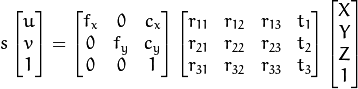
where:
are the coordinates of the projection point in pixels
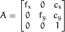
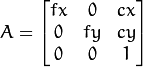
is a camera matrix, or a matrix of intrinsic parameters
is a principal point that is usually at the image center
are the focal lengths expressed in pixel units.
Thus, if an image from the camera is scaled by a factor, all of these parameters should be scaled (multiplied/divided, respectively) by the same factor. The matrix of intrinsic parameters does not depend on the scene viewed. So, once estimated, it can be re-used as long as the focal length is fixed (in case of zoom lens). The joint rotation-translation matrix ![[R|t]](https://docs.opencv.org/2.4/_images/math/fad27ce6ccd005e429215a332c9d7a3a93c8246b.png)
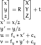
translates coordinates of a point  to a coordinate system, fixed with respect to the camera. The transformation above is equivalent to the following (when
  ):
):
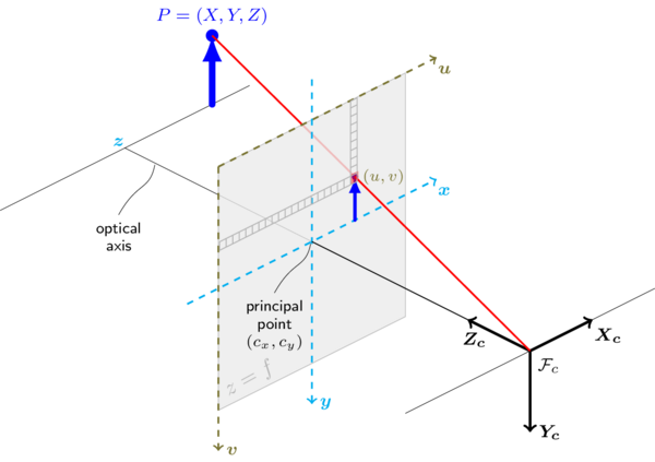
The following figure illustrates the pinhole camera model.
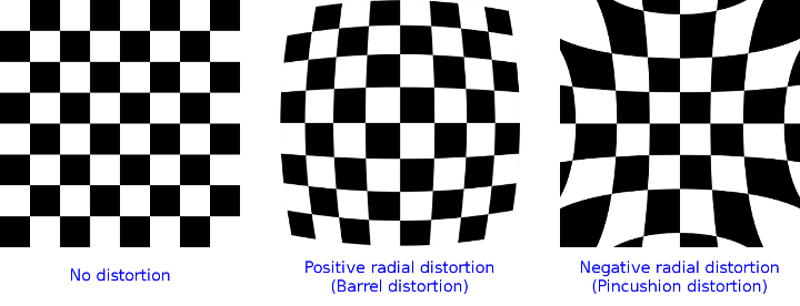
Real lenses usually have some distortion, mostly radial distortion and slight tangential distortion. So, the above model is extended as:
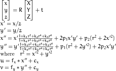
 ,
,  ,
,  ,
,  ,
,  , and
, and  are radial distortion coefficients.
  and
and  are tangential distortion coefficients. Higher-order coefficients are not considered in OpenCV.
The next figure shows two common types of radial distortion: barrel distortion (typically  and pincushion distortion (typically
  ).
).
In the functions below the coefficients are passed or returned as
![(k_1, k_2, p_1, p_2[, k_3[, k_4, k_5, k_6]])](https://docs.opencv.org/2.4/_images/math/c4c47b9554bab572f9e3ea8d7b0be7eeb8b7c6e5.png)
vector. That is, if the vector contains four elements, it means that  . The distortion coefficients do not depend on the scene viewed. Thus, they also belong to the intrinsic camera parameters. And they remain the same regardless of the captured image resolution. If, for example, a camera has been calibrated on images of
 320 x 240 resolution, absolutely the same distortion coefficients can be used for 640 x 480 images from the same camera while  ,
,  ,
,  , and
, and  need to be scaled appropriately.
The functions below use the above model to do the following:
- Project 3D points to the image plane given intrinsic and extrinsic parameters.
- Compute extrinsic parameters given intrinsic parameters, a few 3D points, and their projections.
- Estimate intrinsic and extrinsic camera parameters from several views of a known calibration pattern (every view is described by several 3D-2D point correspondences).
- Estimate the relative position and orientation of the stereo camera “heads” and compute the rectification transformation that makes the camera optical axes parallel.
Note
- A calibration sample for 3 cameras in horizontal position can be found at opencv_source_code/samples/cpp/3calibration.cpp
- A calibration sample based on a sequence of images can be found at opencv_source_code/samples/cpp/calibration.cpp
- A calibration sample in order to do 3D reconstruction can be found at opencv_source_code/samples/cpp/build3dmodel.cpp
- A calibration sample of an artificially generated camera and chessboard patterns can be found at opencv_source_code/samples/cpp/calibration_artificial.cpp
- A calibration example on stereo calibration can be found at opencv_source_code/samples/cpp/stereo_calib.cpp
- A calibration example on stereo matching can be found at opencv_source_code/samples/cpp/stereo_match.cpp
- (Python) A camera calibration sample can be found at opencv_source_code/samples/python2/calibrate.py
calibrateCamera
Finds the camera intrinsic and extrinsic parameters from several views of a calibration pattern.
C++: double calibrateCamera(InputArrayOfArrays objectPoints, InputArrayOfArrays imagePoints, Size imageSize, InputOutputArray cameraMatrix, InputOutputArray distCoeffs, OutputArrayOfArrays rvecs, OutputArrayOfArrays tvecs, int flags=0, TermCriteria criteria=TermCriteria( TermCriteria::COUNT+TermCriteria::EPS, 30, DBL_EPSILON) )
Python: cv2.calibrateCamera(objectPoints, imagePoints, imageSize[, cameraMatrix[, distCoeffs[, rvecs[, tvecs[, flags[, criteria]]]]]]) → retval, cameraMatrix, distCoeffs, rvecs, tvecs
C: double cvCalibrateCamera2(const CvMat* object_points, const CvMat* image_points, const CvMat* point_counts, CvSize image_size, CvMat* camera_matrix, CvMat* distortion_coeffs, CvMat* rotation_vectors=NULL, CvMat* translation_vectors=NULL, int flags=0, CvTermCriteria term_crit=cvTermCriteria( CV_TERMCRIT_ITER+CV_TERMCRIT_EPS,30,DBL_EPSILON) )
Python: cv.CalibrateCamera2(objectPoints, imagePoints, pointCounts, imageSize, cameraMatrix, distCoeffs, rvecs, tvecs, flags=0) → None
| Parameters: |
|
|---|
 . If
. If ![(k_1, k_2, p_1, p_2[, k_3[, k_4, k_5, k_6]])](https://docs.opencv.org/2.4/_images/math/94288b7709d10a7ddf286e33db0074512bda0411.png) of 4, 5, or 8 elements.
of 4, 5, or 8 elements. are set to zeros and stay zero.
The function estimates the intrinsic camera parameters and extrinsic parameters for each of the views. The algorithm is based on [Zhang2000] and [BouguetMCT]. The coordinates of 3D object points and their corresponding 2D projections in each view must be specified. That may be achieved by using an object with a known geometry and easily detectable feature points. Such an object is called a calibration rig or calibration pattern, and OpenCV has built-in support for a chessboard as a calibration rig (see findChessboardCorners() ). Currently, initialization of intrinsic parameters (when CV_CALIB_USE_INTRINSIC_GUESS is not set) is only implemented for planar calibration patterns (where Z-coordinates of the object points must be all zeros). 3D calibration rigs can also be used as long as initial cameraMatrix is provided.
The algorithm performs the following steps:
- Compute the initial intrinsic parameters (the option only available for planar calibration patterns) or read them from the input parameters. The distortion coefficients are all set to zeros initially unless some of
CV_CALIB_FIX_K?are specified. - Estimate the initial camera pose as if the intrinsic parameters have been already known. This is done using
solvePnP(). - Run the global Levenberg-Marquardt optimization algorithm to minimize the reprojection error, that is, the total sum of squared distances between the observed feature points
imagePointsand the projected (using the current estimates for camera parameters and the poses) object pointsobjectPoints. SeeprojectPoints()for details.
The function returns the final re-projection error.
Note
If you use a non-square (=non-NxN) grid and findChessboardCorners() for calibration, and calibrateCamera returns bad values (zero distortion coefficients, an image center very far from (w/2-0.5,h/2-0.5), and/or large differences between and (ratios of 10:1 or more)), then you have probably used patternSize=cvSize(rows,cols) instead of using patternSize=cvSize(cols,rows) in findChessboardCorners() .
See also
findChessboardCorners(), solvePnP(), initCameraMatrix2D(), stereoCalibrate(), undistort()
calibrationMatrixValues
Computes useful camera characteristics from the camera matrix.
C++: void calibrationMatrixValues(InputArray cameraMatrix, Size imageSize, double apertureWidth, double apertureHeight, double& fovx, double& fovy, double& focalLength, Point2d& principalPoint, double& aspectRatio)
Python: cv2.calibrationMatrixValues(cameraMatrix, imageSize, apertureWidth, apertureHeight) → fovx, fovy, focalLength, principalPoint, aspectRatio
| Parameters: |
|
|---|

The function computes various useful camera characteristics from the previously estimated camera matrix.
Note
Do keep in mind that the unity measure ‘mm’ stands for whatever unit of measure one chooses for the chessboard pitch (it can thus be any value).
composeRT
Combines two rotation-and-shift transformations.
C++: void composeRT(InputArray rvec1, InputArray tvec1, InputArray rvec2, InputArray tvec2, OutputArray rvec3, OutputArray tvec3, OutputArray dr3dr1=noArray(), OutputArray dr3dt1=noArray(), OutputArray dr3dr2=noArray(), OutputArray dr3dt2=noArray(), OutputArray dt3dr1=noArray(), OutputArray dt3dt1=noArray(), OutputArray dt3dr2=noArray(), OutputArray dt3dt2=noArray() )
Python: cv2.composeRT(rvec1, tvec1, rvec2, tvec2[, rvec3[, tvec3[, dr3dr1[, dr3dt1[, dr3dr2[, dr3dt2[, dt3dr1[, dt3dt1[, dt3dr2[, dt3dt2]]]]]]]]]]) → rvec3, tvec3, dr3dr1, dr3dt1, dr3dr2, dr3dt2, dt3dr1, dt3dt1, dt3dr2, dt3dt2
| Parameters: |
|
|---|
The functions compute:

where  denotes a rotation vector to a rotation matrix transformation, and
  denotes the inverse transformation. See
 Rodrigues() for details.
Also, the functions can compute the derivatives of the output vectors with regards to the input vectors (see matMulDeriv() ). The functions are used inside stereoCalibrate() but can also be used in your own code where Levenberg-Marquardt or another gradient-based solver is used to optimize a function that contains a matrix multiplication.
computeCorrespondEpilines
For points in an image of a stereo pair, computes the corresponding epilines in the other image.
C++: void computeCorrespondEpilines(InputArray points, int whichImage, InputArray F, OutputArray lines)
C: void cvComputeCorrespondEpilines(const CvMat* points, int which_image, const CvMat* fundamental_matrix, CvMat* correspondent_lines)
Python: cv.ComputeCorrespondEpilines(points, whichImage, F, lines) → None
| Parameters: |
|
|---|
 or
or  matrix of type
 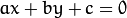 is encoded by 3 numbers
  .
.For every point in one of the two images of a stereo pair, the function finds the equation of the corresponding epipolar line in the other image.
From the fundamental matrix definition (see findFundamentalMat() ), line  in the second image for the point
  in the first image (when
 whichImage=1 ) is computed as:

And vice versa, when whichImage=2,  is computed from
  as:
as:

Line coefficients are defined up to a scale. They are normalized so that  .
.
convertPointsToHomogeneous
Converts points from Euclidean to homogeneous space.
C++: void convertPointsToHomogeneous(InputArray src, OutputArray dst)
Python: cv2.convertPointsToHomogeneous(src[, dst]) → dst
| Parameters: |
|
|---|
The function converts points from Euclidean to homogeneous space by appending 1’s to the tuple of point coordinates. That is, each point (x1, x2, ..., xn) is converted to (x1, x2, ..., xn, 1).
convertPointsFromHomogeneous
Converts points from homogeneous to Euclidean space.
C++: void convertPointsFromHomogeneous(InputArray src, OutputArray dst)
Python: cv2.convertPointsFromHomogeneous(src[, dst]) → dst
| Parameters: |
|
|---|
The function converts points homogeneous to Euclidean space using perspective projection. That is, each point (x1, x2, ... x(n-1), xn) is converted to (x1/xn, x2/xn, ..., x(n-1)/xn). When xn=0, the output point coordinates will be (0,0,0,...).
convertPointsHomogeneous
Converts points to/from homogeneous coordinates.
C++: void convertPointsHomogeneous(InputArray src, OutputArray dst)
C: void cvConvertPointsHomogeneous(const CvMat* src, CvMat* dst)
Python: cv.ConvertPointsHomogeneous(src, dst) → None
| Parameters: |
|
|---|
The function converts 2D or 3D points from/to homogeneous coordinates by calling either convertPointsToHomogeneous() or convertPointsFromHomogeneous().
Note
The function is obsolete. Use one of the previous two functions instead.
correctMatches
Refines coordinates of corresponding points.
C++: void correctMatches(InputArray F, InputArray points1, InputArray points2, OutputArray newPoints1, OutputArray newPoints2)
Python: cv2.correctMatches(F, points1, points2[, newPoints1[, newPoints2]]) → newPoints1, newPoints2
C: void cvCorrectMatches(CvMat* F, CvMat* points1, CvMat* points2, CvMat* new_points1, CvMat* new_points2)
| Parameters: |
|
|---|
The function implements the Optimal Triangulation Method (see Multiple View Geometry for details). For each given point correspondence points1[i] <-> points2[i], and a fundamental matrix F, it computes the corrected correspondences newPoints1[i] <-> newPoints2[i] that minimize the geometric error ![d(points1[i], newPoints1[i])^2 + d(points2[i],newPoints2[i])^2](https://docs.opencv.org/2.4/_images/math/628211a603e8e7dfff3bbfc475051c9b7b84f935.png) (where
(where  is the geometric distance between points
  and
and  ) subject to the epipolar constraint
  .
.
decomposeProjectionMatrix
Decomposes a projection matrix into a rotation matrix and a camera matrix.
C++: void decomposeProjectionMatrix(InputArray projMatrix, OutputArray cameraMatrix, OutputArray rotMatrix, OutputArray transVect, OutputArray rotMatrixX=noArray(), OutputArray rotMatrixY=noArray(), OutputArray rotMatrixZ=noArray(), OutputArray eulerAngles=noArray() )
Python: cv2.decomposeProjectionMatrix(projMatrix[, cameraMatrix[, rotMatrix[, transVect[, rotMatrixX[, rotMatrixY[, rotMatrixZ[, eulerAngles]]]]]]]) → cameraMatrix, rotMatrix, transVect, rotMatrixX, rotMatrixY, rotMatrixZ, eulerAngles
C: void cvDecomposeProjectionMatrix(const CvMat* projMatr, CvMat* calibMatr, CvMat* rotMatr, CvMat* posVect, CvMat* rotMatrX=NULL, CvMat* rotMatrY=NULL, CvMat* rotMatrZ=NULL, CvPoint3D64f* eulerAngles=NULL )
Python: cv.DecomposeProjectionMatrix(projMatrix, cameraMatrix, rotMatrix, transVect, rotMatrX=None, rotMatrY=None, rotMatrZ=None) → eulerAngles
| Parameters: |
|
|---|
The function computes a decomposition of a projection matrix into a calibration and a rotation matrix and the position of a camera.
It optionally returns three rotation matrices, one for each axis, and three Euler angles that could be used in OpenGL. Note, there is always more than one sequence of rotations about the three principle axes that results in the same orientation of an object, eg. see [Slabaugh]. Returned tree rotation matrices and corresponding three Euler angules are only one of the possible solutions.
The function is based on RQDecomp3x3() .
drawChessboardCorners
Renders the detected chessboard corners.
C++: void drawChessboardCorners(InputOutputArray image, Size patternSize, InputArray corners, bool patternWasFound)
Python: cv2.drawChessboardCorners(image, patternSize, corners, patternWasFound) → None
C: void cvDrawChessboardCorners(CvArr* image, CvSize pattern_size, CvPoint2D32f* corners, int count, int pattern_was_found)
Python: cv.DrawChessboardCorners(image, patternSize, corners, patternWasFound) → None
| Parameters: |
|
|---|
The function draws individual chessboard corners detected either as red circles if the board was not found, or as colored corners connected with lines if the board was found.
findChessboardCorners
Finds the positions of internal corners of the chessboard.
C++: bool findChessboardCorners(InputArray image, Size patternSize, OutputArray corners, int flags=CALIB_CB_ADAPTIVE_THRESH+CALIB_CB_NORMALIZE_IMAGE )
Python: cv2.findChessboardCorners(image, patternSize[, corners[, flags]]) → retval, corners
C: int cvFindChessboardCorners(const void* image, CvSize pattern_size, CvPoint2D32f* corners, int* corner_count=NULL, int flags=CV_CALIB_CB_ADAPTIVE_THRESH+CV_CALIB_CB_NORMALIZE_IMAGE )
Python: cv.FindChessboardCorners(image, patternSize, flags=CV_CALIB_CB_ADAPTIVE_THRESH) → corners
| Parameters: |
|
|---|
The function attempts to determine whether the input image is a view of the chessboard pattern and locate the internal chessboard corners. The function returns a non-zero value if all of the corners are found and they are placed in a certain order (row by row, left to right in every row). Otherwise, if the function fails to find all the corners or reorder them, it returns 0. For example, a regular chessboard has 8 x 8 squares and 7 x 7 internal corners, that is, points where the black squares touch each other. The detected coordinates are approximate, and to determine their positions more accurately, the function calls cornerSubPix(). You also may use the function cornerSubPix() with different parameters if returned coordinates are not accurate enough.
Sample usage of detecting and drawing chessboard corners:
Size patternsize(8,6); //interior number of corners
Mat gray = ....; //source image
vector<Point2f> corners; //this will be filled by the detected corners

//CALIB_CB_FAST_CHECK saves a lot of time on images
//that do not contain any chessboard corners
bool patternfound = findChessboardCorners(gray, patternsize, corners,
        CALIB_CB_ADAPTIVE_THRESH + CALIB_CB_NORMALIZE_IMAGE
        + CALIB_CB_FAST_CHECK);

if(patternfound)
  cornerSubPix(gray, corners, Size(11, 11), Size(-1, -1),
    TermCriteria(CV_TERMCRIT_EPS + CV_TERMCRIT_ITER, 30, 0.1));

drawChessboardCorners(img, patternsize, Mat(corners), patternfound);
Note
The function requires white space (like a square-thick border, the wider the better) around the board to make the detection more robust in various environments. Otherwise, if there is no border and the background is dark, the outer black squares cannot be segmented properly and so the square grouping and ordering algorithm fails.
findCirclesGrid
Finds centers in the grid of circles.
C++: bool findCirclesGrid(InputArray image, Size patternSize, OutputArray centers, int flags=CALIB_CB_SYMMETRIC_GRID, const Ptr<FeatureDetector>& blobDetector=new SimpleBlobDetector() )
Python: cv2.findCirclesGridDefault(image, patternSize[, centers[, flags]]) → retval, centers
| Parameters: |
|
|---|
The function attempts to determine whether the input image contains a grid of circles. If it is, the function locates centers of the circles. The function returns a non-zero value if all of the centers have been found and they have been placed in a certain order (row by row, left to right in every row). Otherwise, if the function fails to find all the corners or reorder them, it returns 0.
Sample usage of detecting and drawing the centers of circles:
Size patternsize(7,7); //number of centers
Mat gray = ....; //source image
vector<Point2f> centers; //this will be filled by the detected centers

bool patternfound = findCirclesGrid(gray, patternsize, centers);

drawChessboardCorners(img, patternsize, Mat(centers), patternfound);
Note
The function requires white space (like a square-thick border, the wider the better) around the board to make the detection more robust in various environments.
solvePnP
Finds an object pose from 3D-2D point correspondences.
C++: bool solvePnP(InputArray objectPoints, InputArray imagePoints, InputArray cameraMatrix, InputArray distCoeffs, OutputArray rvec, OutputArray tvec, bool useExtrinsicGuess=false, int flags=ITERATIVE )
Python: cv2.solvePnP(objectPoints, imagePoints, cameraMatrix, distCoeffs[, rvec[, tvec[, useExtrinsicGuess[, flags]]]]) → retval, rvec, tvec
C: void cvFindExtrinsicCameraParams2(const CvMat* object_points, const CvMat* image_points, const CvMat* camera_matrix, const CvMat* distortion_coeffs, CvMat* rotation_vector, CvMat* translation_vector, int use_extrinsic_guess=0 )
Python: cv.FindExtrinsicCameraParams2(objectPoints, imagePoints, cameraMatrix, distCoeffs, rvec, tvec, useExtrinsicGuess=0) → None
| Parameters: |
|
|---|
 .
.The function estimates the object pose given a set of object points, their corresponding image projections, as well as the camera matrix and the distortion coefficients.
Note
- An example of how to use solvePNP for planar augmented reality can be found at opencv_source_code/samples/python2/plane_ar.py
solvePnPRansac
Finds an object pose from 3D-2D point correspondences using the RANSAC scheme.
C++: void solvePnPRansac(InputArray objectPoints, InputArray imagePoints, InputArray cameraMatrix, InputArray distCoeffs, OutputArray rvec, OutputArray tvec, bool useExtrinsicGuess=false, int iterationsCount=100, float reprojectionError=8.0, int minInliersCount=100, OutputArray inliers=noArray(), int flags=ITERATIVE )
Python: cv2.solvePnPRansac(objectPoints, imagePoints, cameraMatrix, distCoeffs[, rvec[, tvec[, useExtrinsicGuess[, iterationsCount[, reprojectionError[, minInliersCount[, inliers[, flags]]]]]]]]) → rvec, tvec, inliers
| Parameters: |
|
|---|
The function estimates an object pose given a set of object points, their corresponding image projections, as well as the camera matrix and the distortion coefficients. This function finds such a pose that minimizes reprojection error, that is, the sum of squared distances between the observed projections imagePoints and the projected (using projectPoints() ) objectPoints. The use of RANSAC makes the function resistant to outliers. The function is parallelized with the TBB library.
findFundamentalMat
Calculates a fundamental matrix from the corresponding points in two images.
C++: Mat findFundamentalMat(InputArray points1, InputArray points2, int method=FM_RANSAC, double param1=3., double param2=0.99, OutputArray mask=noArray() )
Python: